?
i think the output capacitor connects wrong place , it should touch the joint of 0.33 and 47K resistor
i think the output capacitor connects wrong place , it should touch the joint of 0.33 and 47K resistor
Thanks!
Yes, the output capacitor should connect on the other side of 47k resistor, on the joint with 0.33 ohm. I made a mistake while drawing the line🙁
However, this is minor. What confuses me is the 470k resistor (marked red) I am not sure if it is needed if the mosfet is cascoded, as it is.
As I imagine, I hope this will work as a current amplifier, won't it?
Maybe somebody can clarify this.
Mr. Pass? Grey?🙂
Thanks,
Vix
Vix said:
As I imagine, I hope this will work as a current amplifier, won't it?
Vix
My understanding , from some previous building tests , is that the buffer will put the gain of the amplifier at a much high level not suitable for this application, unless you use some ac feedback .
Hi Stefano!
As I understand, the buffer is there only to provide better impedance match, not a gain. Maybe I am wrong, that's why I am asking.
Thanks!
Vix
As I understand, the buffer is there only to provide better impedance match, not a gain. Maybe I am wrong, that's why I am asking.
Thanks!
Vix
I think the amp will work properly.
The 440 k resistor is needed to supply biasvoltage to the fet and a small amount of neg feedback at DC to stabilize the circuit.
You can adjust the gain by changing the 1,00 ohm resistor connecting the bottom fet with ground to higher values to decrese the gain and lower values to increse the gain of the amp.
Yes, the amp is a currentamp. It will have roughly the outputZ that you place in parralell with the output.
Mvh, Johannes.
In the above drawing I think the output capacitors are connected too the right place.i think the output capacitor connects wrong place , it should touch the joint of 0.33 and 47K resistor
Hi
Thanks for the replies!
IRFP9601 is a P channel fet, used as a buffer. The idea is "borrowed" from ZEN V4, except that I chose IRFP9610 instead of ZVP 3310, just because I have it "in stock"🙂
I hope this should work well.
Regards,
Vix
Thanks for the replies!
IRFP9601 is a P channel fet, used as a buffer. The idea is "borrowed" from ZEN V4, except that I chose IRFP9610 instead of ZVP 3310, just because I have it "in stock"🙂
I hope this should work well.
Regards,
Vix
Hi,
I meant IRF9610. Other three Fets are IRFP250N. The scanned schematic is not clear. Sorry.
Thanks,
Vix
I meant IRF9610. Other three Fets are IRFP250N. The scanned schematic is not clear. Sorry.
Thanks,
Vix
I would like to load the inputbuffer with a CCS instead. Any and all noise and hum that appear on the gate of Q1 will be amplified by the amp.
I would also suggest connecting 220 ohm between inputcap and 440 kohm/100kohmpot node.
Just a stabillity thing, it might not be needed but....
Johannes.
I would also suggest connecting 220 ohm between inputcap and 440 kohm/100kohmpot node.
Just a stabillity thing, it might not be needed but....
Johannes.
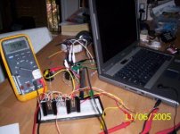
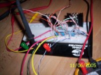
I'd like to share some pictures of my on-going Zen-F2 headphone amp now playing Men@Work with my laptop as source and my cellphone earphone as load😀 With all the messy wiring/grounding some white noise filters through with music. Can't say how sweet it is yet with this set-up. Will report back as soon as I clean it up with a pcb.
Attachments
Member
Joined 2002
Just out of curiousity, what would the voltage/amperage ratings for the rectifier diodes be for the F2 circuit?
Thanks,
KT
Thanks,
KT
Current draw for the F2 circuit is 2.8 amps per channel as Nelson design it but you should take in consideration that at start-up the current will be much greater until the filter caps on the power supply are up to the operating voltage which usually takes around one second depending on the PSU arrangement and cap size.
A usual practice is to have a 30 amp. diode bridge at the PSU for power amps. I would say that voltage rating for this bridge should be at least 100V.
A usual practice is to have a 30 amp. diode bridge at the PSU for power amps. I would say that voltage rating for this bridge should be at least 100V.
I have suffered a slight setback in finishing this amp😀
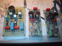
The boards are nearly finished, but then... I happened to get 8 great heatsinks for nothing. They were in the scrap container, and a nice guy knowing my likeings😉 Did get my attention to those. Here is a pic of Apassgears very nice right/left boards!
As you can see, I am soldrering up a BoZ to give the F2 perfect conditions.
Steen🙂
Attachments
Hmmm, quoting myself, would that be right NP??🙂As you can see, I am soldrering up a BoZ to give the F2 perfect conditions.
Steen😎
Member
Joined 2002
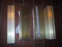
steenoe said:Here is a pic of some of those sinks. My intention is to make both the F1 and F2 in twin "casas"😉
Tony, the resistor to the LED, is 3K about right?
Steen😎
Those are some nice Heat sink's
That was what I thought!! How lucky can a guy get?? I mean 8 of those for free😀 😀 I just love my job😉Those are some nice Heat sink's
Steen😎
Ps Just to pour some salt in the wound, I am having the alu plates to finish the chassis comming my way too😎
- Status
- Not open for further replies.
- Home
- Amplifiers
- Pass Labs
- F2 Initial Listening Impressions