Troubles with EZDUAL
Hi Guys,
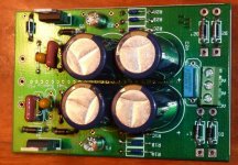
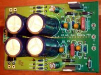
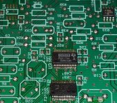
I put together my EZDual tonite, and am having problems with it. Trafo reads 15.1v - 0v - 15.1v, the centertap is hooked to AC2, something seems to be pulling current with no load. I get 13.4V -0v - 13.4V from the trafo when hooked up to the board. With power hooked up R2A,B,C get warm. Even if I disonnect AC3 and leave AC1 hooked up R2A,B,C gets warm. I checked for obvious shorts, but so far I haven't been able to find any. I'm pretty much a newby at electronics, and any help would be appreciated. I've attached some pics of my build.
Thx,
PJN
Hi Guys,
I put together my EZDual tonite, and am having problems with it. Trafo reads 15.1v - 0v - 15.1v, the centertap is hooked to AC2, something seems to be pulling current with no load. I get 13.4V -0v - 13.4V from the trafo when hooked up to the board. With power hooked up R2A,B,C get warm. Even if I disonnect AC3 and leave AC1 hooked up R2A,B,C gets warm. I checked for obvious shorts, but so far I haven't been able to find any. I'm pretty much a newby at electronics, and any help would be appreciated. I've attached some pics of my build.
Thx,
PJN
Attachments
First check the polarity of the tantalum capacitors C4,5,7,8. Especially C7 & 8, the + side of each should connect to Ground.
Then check the DC output voltage. If it's slowly decreasing after you wait a few seconds, it is probably those capacitors. I'd bet on C8 causing the problem.
Oh, yes, wear eye protection! They can explode.
If you know for sure that a tantalum capacitor has been reverse- or over-voltaged, replace it even if it seems okay.
Hi All,
I'm starting to order parts for my DAC board. On the BOM posted for the 1.5 EZDAC on Evan's site C1,2,4,5,7,8,10 & 12 are shown as 10 uF, however when I go to the digitkey number shown on the BOM they are shown as 100 uF, on the digitkey site. Could anyone please let me know the right value ?
Thanks,
PJN
They are supposed to be 10uF, tantalums originally. The 100uF are way too big to fit on the board. You can use the 399-3654-ND if you like, but anything between 10...47uF and 16V or higher is o.k.
I fitted small Rubycon ZA there, here's my BOM.
Regards,
Ray
Thanks Paul,
The tantalums are reversed, I wasn't aware that tantalums had polarity and the tiny writing was very hard to see. I'll swap them out and give it another try.
Ray, thanks for the BOM.
The tantalums are reversed, I wasn't aware that tantalums had polarity and the tiny writing was very hard to see. I'll swap them out and give it another try.
Ray, thanks for the BOM.
Yes, there's a tiny 'plus' sign on the case if you're lucky, sometimes it's only a stripe that indicates the minus.
But it's going to make music now 🙂
Ray
But it's going to make music now 🙂
Ray
I used 0.1uF ceramics. I plan to parallel the LM337 one with something larger; the datasheet recommends >= 1 uF, I think. The LM317 should be happy with the 0.1uF. If you use something way bigger, I'd recommend parallelling it with a 0.1 ceramic, for low impedance at high frequencies.They are supposed to be 10uF, tantalums originally. The 100uF are way too big to fit on the board. You can use the 399-3654-ND if you like, but anything between 10...47uF and 16V or higher is o.k.
I fitted small Rubycon ZA there, here's my BOM.
Regards,
Ray
http://www.national.com/ds/LM/LM117.pdf
http://www.national.com/ds/LM/LM137.pdf
Last edited:
Hi Guys,
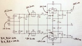
I removed R7 and R8 and replaced them with some electrolytics that I picked up at Radio shack. The good news is that solved the heating up problem, the bad news it that I'm getting+/- 18.5 vdc on the psu outlet. It looks like something is going on in the regulator area. I've attached a pic of some voltage measurements that I've taken. I'm am a bit confused by all of the different BOM's for the PSU so I'm wondering if I used the correct choice of resistors.
PJN
Attachments
Hi Ray,
That was a good read, thanks. I got the values for R4 and R6 from the fancy BOM, and the values for R3 & R5 from post #119. I do have some 1K1's so I'll swap R4 & R6.
PJN
That was a good read, thanks. I got the values for R4 and R6 from the fancy BOM, and the values for R3 & R5 from post #119. I do have some 1K1's so I'll swap R4 & R6.
PJN
I see, both BOM's list values that won't give you 12V or 15V... confusing 😕
Now you know how they work, and able to calculate the correct values for no more troubles in the future 😀
Ray
Now you know how they work, and able to calculate the correct values for no more troubles in the future 😀
Ray
Last edited:
Yea it is confusing especially if you don't know what you're doing like me. I'm glad I have your BOM for the EZDAC.
Yea it is confusing especially if you don't know what you're doing like me. I'm glad I have your BOM for the EZDAC.
If you're using the LM317/37, make sure to read the datasheet. The formula for calculating voltage is very simple (assuming the adjust current is negligible). I always assume people don't take my BOM values on blind faith, but I suppose that has not been the case.
I did run across this as a USB-SPDIF kit:
The γ1 Modular Miniature DAC configuration C, USB-SPDIF
I want a relay to switch between USB and SPDIF and am looking at if it's feasible with this kit.
Their headphone amps look good too.
The γ1 Modular Miniature DAC configuration C, USB-SPDIF
I want a relay to switch between USB and SPDIF and am looking at if it's feasible with this kit.
Their headphone amps look good too.
Last edited:
Hi All,
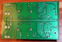
After watching a primer on SMD soldering on U tube I finally got the courage up to try any start populating the DAC board. It wasn't so bad after all. I do have a question on the orientation of U 4 and U5. In the picture that I've seen folks used the AD8610, but I used the LME4971 since digikey was out of the AD8610. In the attached pic I have U2 and U3 attached, but U5 is just sitting there. Is the LME4971 in the proper orientation to solder in ?
Thanks,
PJN
Attachments
Looks right to me. Pin 1 (not connected) would be the lower left pin there right next to pin 2 which is under the "MA".
Evan,
Thanks for the info, I'll try to post more info as the build progresses so others can avoid my mistakes.
PJN
Thanks for the info, I'll try to post more info as the build progresses so others can avoid my mistakes.
PJN
I'm happy to report that my ezdac is up and running. I'm working on it as lunchtimes permit at my workplace (where I have access to SMD rework equipment). I used an SPDIF output from my PC, with a small passive network to change from 'TTL' to the proper level, to test it.
Now it's time to turn my attention to the companion USB/SPDIF board that I mentioned in some previous posts. Hope to have a schematic sometime next week.
Now it's time to turn my attention to the companion USB/SPDIF board that I mentioned in some previous posts. Hope to have a schematic sometime next week.
A new star is born , thanks Evan.
An externally hosted image should be here but it was not working when we last tested it.
- Status
- Not open for further replies.
- Home
- Source & Line
- Digital Line Level
- ezDAC v.1.5 Builders Thread