done some reading and now understand that adding limiting resistors was not a good idea - my sec resistance from ct to terminal is 220r
and from the data of the EZ81 i understand that Rt min is 200
so probaly the caps are too big and drowing too much current ?
i still dont understand way C1 being the first cap, didnt fail ?
and from the data of the EZ81 i understand that Rt min is 200
so probaly the caps are too big and drowing too much current ?
i still dont understand way C1 being the first cap, didnt fail ?
It should not spark if you wired it correctly.
I don't see why you placed a 100ma fuse in the CT of power transformer
You should place them in the secondary (2 fuses)
The fuse on the heater too is not necessary.
Check the caps + - resistance it should be high.
I don't see why you placed a 100ma fuse in the CT of power transformer
You should place them in the secondary (2 fuses)
The fuse on the heater too is not necessary.
Check the caps + - resistance it should be high.
hi gabdx
wired it correctly they would not work at all if not
i placed a fuse on the CT to protect the tr sec circuits - the ct is common to both
i checkt the caps with a digital capacitance meter and they show ok
wired it correctly they would not work at all if not
i placed a fuse on the CT to protect the tr sec circuits - the ct is common to both
i checkt the caps with a digital capacitance meter and they show ok
hi gabdx
wired it correctly they would not work at all if not
i placed a fuse on the CT to protect the tr sec circuits - the ct is common to both
i checkt the caps with a digital capacitance meter and they show ok
ok ,
check caps for resistance, they should be high resistance.
Maybe other members of the forum will tell you that the fuses should not be in CT as I don't think it protects adequately.
The CT should be wired to the Ground from incoming 3 prong connector and send any voltage to the ground, it is the primary that you should fuse.
For more protection you should fuse the secondary with 2 fuses,
: if the CT fuse that you have right now blow there is still potential in the circuit the transformer can operate normally without any CT connection !

when i first open the amp it was working no problems😕
i took v measurements from the psu
on c1 368v
10h chock
c2 356v
1k res
c3 308v B+
48v/1000 =48mA that is the correct current for 2 x 12B4 or i am wrong?
i cant understand what happend ?
could it be that the 12B4 are bad or sockets loose and the psu runs with no load drowing to much current?
tnx for your help
WHO mentioned fusing filament CT?No need to fuse heater supplies. The CT on a heater supply does a completely different job from the CT on a high voltage secondary, so fusing the heater CT achieves worse than nothing: it simply inserts a point of failure while protecting nothing. Think about where the currents flow.
Where do you pull that from?
Fusing filament windings is *required* by several Electrical Safety agencies around the World.
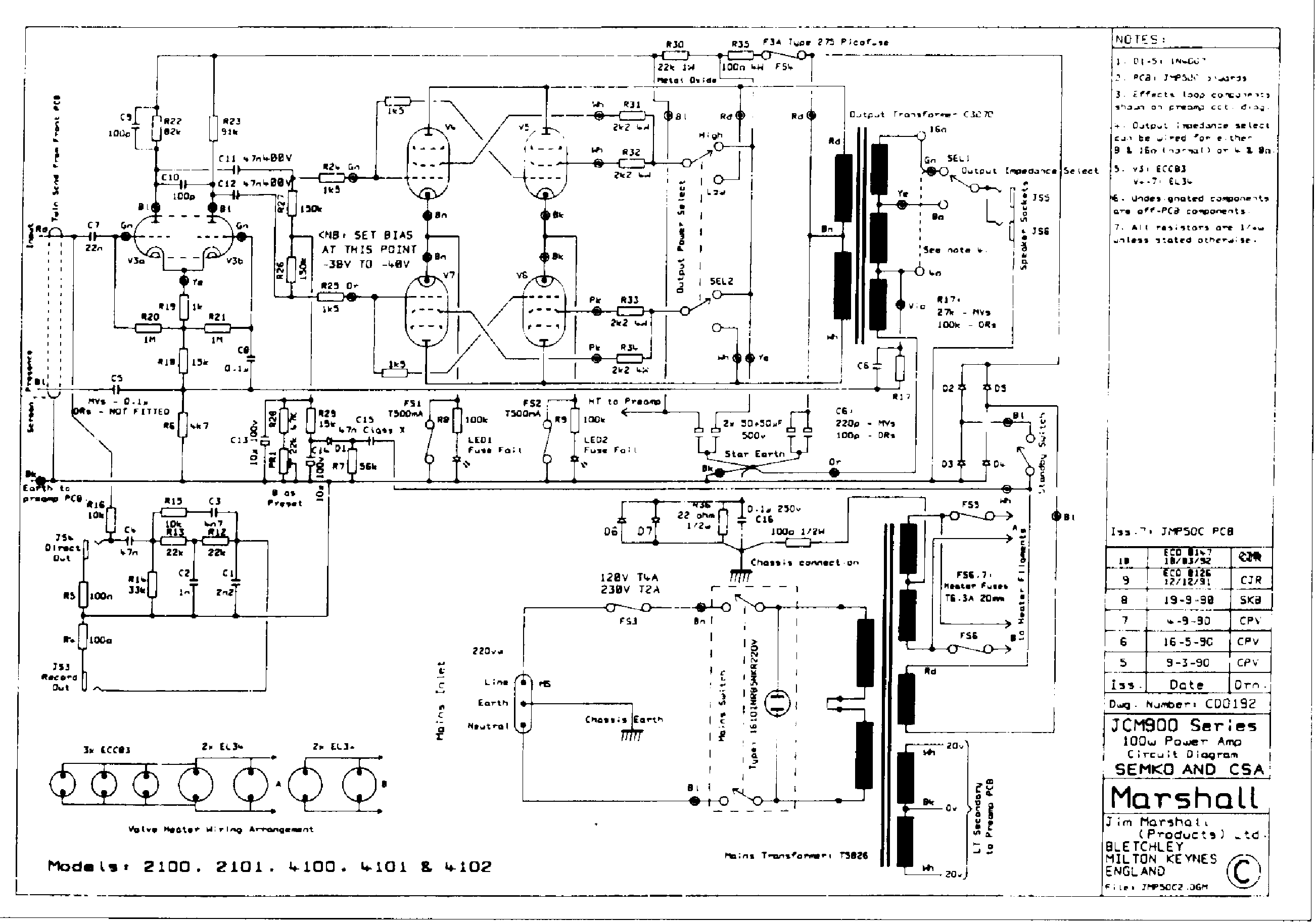
Check this Marshall Amplifier showing *mandatory* filament winding fusing ... on both hot wires of course, not on center tap which by the way, might even be virtual/artificial , just 2 x 100 ohm resistors.
Needed to get CSA and SEMKO approval.
In fact, standards have been updated since ... but the fusing requirement has not been dropped.
Note: if hard to read: "F6/F7 heater fuses - T6.3A 20mm"
And not news either, this schematic is from 1990 !!!! 😱
hi Osvaldo
the sparks ( ark ) on the positive terminal of the caps c3 or c2
not ez81 and not on c1
the sparks ( ark ) on the positive terminal of the caps c3 or c2
not ez81 and not on c1
as I wrought before I started the preamp and the B+ was a bit high 308V
so I replaced the 1K resistor with a 1.2K and then problems started…
sparks & smoke from the positive terminal on C3 100Uf/450V (not 500V like in the schema)
I replaced it back to 1K but still S&S from C3
Replaced the cap with a 47Uf/400V so I got S&S from positive terminal on C2
I thought maybe the current is to high so I tried putting limiting resistor between the cathode and C1 then the fuse on the CT of the HT blew
When disconnecting the smoothing circuit and measuring from the rectifier I get 292VDC and the from TR 635VAC
The chock is 10H/80ma with 200R DC
To my understanding probably too much current?
Last edited:
Note: if hard to read: "F6/F7 heater fuses - T6.3A 20mm"
And not news either, this schematic is from 1990 !!!! 😱
This is true for the case you make equipment to sale to thirty persons, but in our, whose devices are for personal use, I don't think it be necessary.
I can only think that the link to the capacitor is damaged.
maybe the ground link or the power link, check that the choke is alright and has no intermittent contacts output/input.
Maybe the capacitor has a weak contact on (+) or (-) which sparks.
maybe the ground link or the power link, check that the choke is alright and has no intermittent contacts output/input.
Maybe the capacitor has a weak contact on (+) or (-) which sparks.
hi gabdx
i checked the caps with a multimeter for resistance
c1 starts 0.5M and rise to 2.5M +
c2 stops rising at 0.5M
c3 rising to 4.5M+
they all show correct values in farads
the choke is alright (205R)
i checked the caps with a multimeter for resistance
c1 starts 0.5M and rise to 2.5M +
c2 stops rising at 0.5M
c3 rising to 4.5M+
they all show correct values in farads
the choke is alright (205R)
Hi paltal,
For a spark to arise you need to have a bad connection.
If the (+) terminal has sparks it must be with something like the cap body or the connecting pin. You cannot have sparks on a straight wire, something is fishy o.o
For a spark to arise you need to have a bad connection.
If the (+) terminal has sparks it must be with something like the cap body or the connecting pin. You cannot have sparks on a straight wire, something is fishy o.o
hi
it looks like through the pvc isolation to the body
the caps terminals are the snap mount kind
when replaced with other caps allso sparks
it looks like through the pvc isolation to the body
the caps terminals are the snap mount kind
when replaced with other caps allso sparks
Hi
I checked the valves pins on the 12b4 and the ez81 and they full of corrosion and show poor continuity
Is it possible that I turned on the amp the psu had no load so the voltage was too high and c3 the last cap 100uf/450v broke and an ark formed to itself?
After replacing c3 I also changed the resistor between c2 to c3 (from 1k to 2k7) so c2 broke and an ark formed to itself, may be? because the high voltage was now on c3?
Does it sound like a plausible theory?
I must understand what happened before I continue
Thank you
May be, but it is symptom of a very bad design.Hi
I checked the valves pins on the 12b4 and the ez81 and they full of corrosion and show poor continuity
Is it possible that I turned on the amp the psu had no load so the voltage was too high and c3 the last cap 100uf/450v broke and an ark formed to itself?
After replacing c3 I also changed the resistor between c2 to c3 (from 1k to 2k7) so c2 broke and an ark formed to itself, may be? because the high voltage was now on c3?
Does it sound like a plausible theory?
I must understand what happened before I continue
Thank you
Sparks may then be because the cap sometimes can "catch" voltage, and when doing it, draws lots of milliamperes, producing the arc. Also, surely, the soldered join inside will be carbonized by the sparking.
Hi osvaldo
Is it possible that the first time I open the amp everything was working fine for minutes and switching's on and off for testing, and the day after everything changed?
I am trying to understand if the design is wrong, and what's wrong with it
Thank you
Is it possible that the first time I open the amp everything was working fine for minutes and switching's on and off for testing, and the day after everything changed?
I am trying to understand if the design is wrong, and what's wrong with it
sorry but i dont understand ... ?cap sometimes can "catch" voltage
Thank you
Hi osvaldo
Is it possible that the first time I open the amp everything was working fine for minutes and switching's on and off for testing, and the day after everything changed?
I am trying to understand if the design is wrong, and what's wrong with it
sorry but i dont understand ... ?
Thank you
I apologize for the inconveniences. I want to mean, that when cap is discharged, and voltage appears, the cap try to charge from it. If there is a non good contact, then the high voltage gradient in the site causes a spark to appear, then charging at some level, the cap. but if cap didn't acquired full voltage, then another time voltage gradient appears, trying to charge again, thus the cycle repeats until cap is fully charged, then, never.
Thanks for your answer Osvaldo
I should apologize for my lack of understanding in electronics …😱
So may be bad soldering at cap terminals or tube pins contacts?
Or a total fault in the design of the psu for this amp?
I should apologize for my lack of understanding in electronics …😱
So may be bad soldering at cap terminals or tube pins contacts?
Or a total fault in the design of the psu for this amp?
If when load is removed, and voltage on the PSU becomes greater than the rated voltage of the caps, then a serious design error had been done.Or a total fault in the design of the psu for this amp?
Last edited:
It would be nice to see a video on youtube...
I recently miss-bias some amps and was running el34 at 50 watts bias (33W is the design max...) for hundred of hours and nothing bad happened fortunately!
The capacitors might repair itself... please clean socket pins and your rectifier pins properly before using them.
After the spark the parts should be thoroughly cleaned of any deposits which could trigger another spark. Check the insulation to ground of every part and take voltage measurements with the amplifier turned on to see if the voltages are stable.
Always make sure you don't touch anything when testing. Isolate yourself from any basement, metals and use a GFCI plug.
Preinstall voltmeters with secured connections, then remotely power the amplifier with a disconnect switch, disconnect all power plugs then take more measurements the same way!
- Status
- Not open for further replies.
- Home
- Amplifiers
- Power Supplies
- EZ81 power supply