Thank you guys
For further testing's I intend to use caps in series with balancing resistors
From what I manage to find locally
C1 – 2 x 47uf/400v with 220k res on each cap = 33uf/800v
C2 – 2 x 100uf/450v with 150k res on each cap = 50uf/900v
C3 – 2 x 100mf/400v with 150k res on each cap = 50uf/800v
The HT voltage was around 300v
Hope I am right with the resistors, what do you think?
And if it checks ok I will replace with the caps that are 500v from before 😱 and order caps with the correct voltage ratings instead of damaged caps
Tnx for the warning tips, I am being very careful to compensate for my little understanding in electronics😉
Hi again
I changed the caps like in the post above and everything was working fine… and then sparks again from the rectifier socket pin no 1 anode
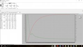
When I run it in psud no warnings ?? and the data is very close to what I I get in the amp
My Rs is 283Ω
When I place 1n4007 silicon diodes before each anode I don't get sparks
Does anybody have an idea please ?
I am trying to understand why and remove the silicon
tnx
I changed the caps like in the post above and everything was working fine… and then sparks again from the rectifier socket pin no 1 anode
When I run it in psud no warnings ?? and the data is very close to what I I get in the amp
My Rs is 283Ω
When I place 1n4007 silicon diodes before each anode I don't get sparks
Does anybody have an idea please ?
I am trying to understand why and remove the silicon
tnx
EZ81 has an unused or no internal connection pin between anodes, and cathode and heater. Do the sparks appear between this pins, the anodes and ground, cathode and ground, cathode and heaters pins, or where?
Hi
the sparks, more like a small welding ark, starts after 20 – 30 sec from the moment the psu reaches working voltage
it is from pin 1 (anode) to the ceramic of the socket, it seems that it is trying to make a path to pin no 2 (not in use)
installed 2 x 1n4007 no problem
changed the socket, now I can hear the ark but can't see it
changed the tube, same thing
installed,again 2 x 1n4007 no problem
the 2 tubes are Nos Haltron from the 60 – 70
when I check with a multimeter between pins 1 and 7 I get 646 VAC
on C1 there is 375 VDC
B+ 268 VDC
tnx
and a happy new year
This sort of voltage was routinely handled by old B9A valve sockets. Maybe modern sockets are no good, or maybe you haven't wired it right? Is the valve socket clean?
i will try and clean the socket again and check the welding
i remember that one time during the tests the rectifier didn't work because not siting well in the socket, will try and find a third socket
tnx
i remember that one time during the tests the rectifier didn't work because not siting well in the socket, will try and find a third socket
tnx
Hi again
Cracked the socket open into two halves, up and bottom
There is a visible black trace between pin 1 anode and pin 3 cathode
I think the trace went thru the gunk of soldering paste residues that leaked inside the space of the socket (my bad soldering technics…)
Found an old socket, soak it in acetone overnight, try again tomorrow
What is the potential between anode and cathode?
700v – 800v ?
Just use good quality electronic solder with built-in flux cores. No need for anything else. Learn a good soldering technique.
- Status
- Not open for further replies.
- Home
- Amplifiers
- Power Supplies
- EZ81 power supply