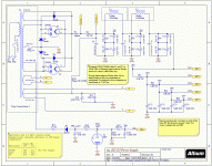
New project on the works, just finished the schematics and layout and looking for some kind feedback before I ink a couple of prototypes. Their is nothing really new or revolutionary about the design. It was a mash up of a couple of amps that I liked the topology (not that I know much) such as the Grommes 215, Heathkit etc.
I have a lot of 6SN7GTB's and figured that was the starting point, the ability to drive a pair or quad of KT88's or KT120's should be a fine higher powered amp. I also like the glowing OB2 bias regulator, but this can easily be left off the project if desired as well as some other odd options I tossed in such as either tube or solid state rectifiers.
I had good success with the EZ10 (6V6 PP Monoblock) and the EZ260 (Grommes 260A clone) and figured I would again hit the design with a PCB for easy and repeatable assembly, if you want to do point to point knock yourself out will be just as fun to build.
PCB Size is 9.5" x 10" with everything on it except power transformers and chokes so it can hopefully fit on one of the larger Hammond cases (I will only be using one for testing, better options available now...)
I had a couple of custom Heyboer transformers made that should get the output into the 125w range if all goes well, but will have to see if I spec'ed the power transformer correctly.
What's not completed -
Final values for dropping resistors for the 6SN7 to get the load lines were I think they might need to be.
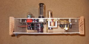
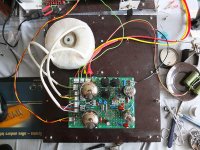
Pictured of the schematic and parts placement below!
I have a lot of 6SN7GTB's and figured that was the starting point, the ability to drive a pair or quad of KT88's or KT120's should be a fine higher powered amp. I also like the glowing OB2 bias regulator, but this can easily be left off the project if desired as well as some other odd options I tossed in such as either tube or solid state rectifiers.
I had good success with the EZ10 (6V6 PP Monoblock) and the EZ260 (Grommes 260A clone) and figured I would again hit the design with a PCB for easy and repeatable assembly, if you want to do point to point knock yourself out will be just as fun to build.
PCB Size is 9.5" x 10" with everything on it except power transformers and chokes so it can hopefully fit on one of the larger Hammond cases (I will only be using one for testing, better options available now...)
I had a couple of custom Heyboer transformers made that should get the output into the 125w range if all goes well, but will have to see if I spec'ed the power transformer correctly.
What's not completed -
Final values for dropping resistors for the 6SN7 to get the load lines were I think they might need to be.
Pictured of the schematic and parts placement below!
Attachments
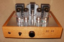
I built a quad KT88/KT90 unit. It was a huge learning curve for me, and quite an adventure! Oscillation was a problem, mainly due to my inexperience with driver circuits. At the end of the summer, I plan on doing a circuit revision.
I recommend, from my own experience:
- Get rid of those 5U4's! You have silicon diodes across them but the filaments of the rectifiers will reduce the efficiency of your system plus up the cost considerably. More heat will be generated too. My unit I can feel the heat about three feet away! The relay in your system will allow ample warm up time.
- The B+ is unregulated. Why do you need to regulate the bias supply? You can reduce cost and complexity here.
- Ditch PCB construction unless a chassis covers everything except for holes to allow for tube protrusion. PCBs and very high heat do not mix unless some military grade FR4 type substance is used. FR4 is rated to 140C. Id imagine a tube amp with the right ambient temperature can easily get that hot!
- Watch the maximum voltage for your B+ timer relay. Too low a rating will cause arcing. Eventually the contacts will weld shut. With the August revision to my amp, I will add a solid state FET based relay that can handle 1KV across it.
- Get rid of one of the filter chokes. A PP stage will reject most of the hum and will make your circuit cheaper. My system uses only a dual capacitor bank and a 600mH filter inductor.
- Simplify your driver circuit. You do not need the cathode followers.
- Reduce the driver so there are not two cap coupled stages with a global feedback loop. According to Morgan Jones and my own experience, more poles will be added to your system. That will make it more prone to whistling and motorboating 🙁 . Those early Williamson amplifiers were notorious for taking out tweeters due to their coherent instability!
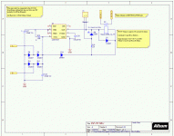
Here is a schematic for the Rev. 2 of my PPP amp which will be completed over the summer. The driver is for a 60 watt unit (just finished a MKIII mod). According to simulation, with less global feedback, it will work in a 120 watt unit.
If the 12BH7 does not possess sufficient headroom for the 80 odd volts pk-pk (required for 125-130 watts into 8 ohms), I probably will try for a higher gain phase splitter, like a 12AT7 used in Fender amplifiers. I will then swap the 12AY7 for a 12AU7 or 12BH7 and tweak the feedback.
Note that this circuit will be revised. I definitely will not be using the power supply shown in the schematic as it is too inefficient.
Attachments
Why the 36 second B+ delay? The biggest capacitor inrush happens at the first few seconds. After 36 seconds the KT88's will have reached their max conductivity some time ago. During this, the inrush resistor will probably starve the main PSU caps and HT can not rise to it's intended voltage anyway. Applying full B+ when the KT88's are warmed up isn't a good idea. It can stress the PSU.
Edit: I see the main caps are right next to the power tubes. They get seriously hot. Heat and electrolytic caps don't play well together, plus, the KT-88's diameter is wider then it's base.
Edit: I see the main caps are right next to the power tubes. They get seriously hot. Heat and electrolytic caps don't play well together, plus, the KT-88's diameter is wider then it's base.
Last edited:
I built a quad KT88/KT90 unit. It was a huge learning curve for me, and quite an adventure! Oscillation was a problem, mainly due to my inexperience with driver circuits. At the end of the summer, I plan on doing a circuit revision.
I recommend, from my own experience:
- Get rid of those 5U4's! You have silicon diodes across them but the filaments of the rectifiers will reduce the efficiency of your system plus up the cost considerably. More heat will be generated too. My unit I can feel the heat about three feet away! The relay in your system will allow ample warm up time.
- The B+ is unregulated. Why do you need to regulate the bias supply? You can reduce cost and complexity here.
- Ditch PCB construction unless a chassis covers everything except for holes to allow for tube protrusion. PCBs and very high heat do not mix unless some military grade FR4 type substance is used. FR4 is rated to 140C. Id imagine a tube amp with the right ambient temperature can easily get that hot!
- Watch the maximum voltage for your B+ timer relay. Too low a rating will cause arcing. Eventually the contacts will weld shut. With the August revision to my amp, I will add a solid state FET based relay that can handle 1KV across it.
- Get rid of one of the filter chokes. A PP stage will reject most of the hum and will make your circuit cheaper. My system uses only a dual capacitor bank and a 600mH filter inductor.
- Simplify your driver circuit. You do not need the cathode followers.
- Reduce the driver so there are not two cap coupled stages with a global feedback loop. According to Morgan Jones and my own experience, more poles will be added to your system. That will make it more prone to whistling and motorboating 🙁 . Those early Williamson amplifiers were notorious for taking out tweeters due to their coherent instability!
Thanks for the comments, some misunderstanding about the schematics.
1. The 5u4's are optional if you like tube rectifiers, if you do, no need for the diodes, or use diodes and lose the
2. Bias supply is again an option to use the ob2, can remove tube and use like a regular bias tap. I like the extra tube, have plenty of ob2's and the amp I previously built sounds great with them so left it in.
3. PCB is fine, have run all the amps I have built with no problems with 6 hours a day on time for months. Have not seen any PCB issues with standard FR4. High temp upgrade to the pcb is about 5 bucks for the board which may be done this time around. Chassis is just that an opening for just the tubes, as the other amps and seems to ventilate well.
4. Chokes are optional as well, simple jumper to remove in or out of circuit. Cost was not an issue. For the driver stages I would expect them to be beneficial with some ripple reduction. Again, can go either way with a jumper on the board.
5. B+ Rating on the relay, this is a tricky one and one more of an experiment. The idea is not to switch the relay on until caps have charged and the load across the resistor is low (after caps charge) which would eliminate switching much current. Again this is more of an experiment and will require some testing to get right I'm guessing. The value of 33k was a quick guess that would sustain 5 watts or so at full voltage. Still needs some thinking.
6. Driver circuits, I am learning too and figured I would give the cathode follower circuit a try. I have seen it in a few amps and results seem to be favorable. Again, not worried about cost or complexity, just giving it a try and if I wanted to wire in another pair of kt88 I would have plenty of drive for it 😉
Thanks for the comments, the basic circuit is really nothing new, much from a couple of commercial amps that have had good reviews.
Will see how it practically goes, drawing the picture and building one are miles apart!
Sandy
Why the 36 second B+ delay? The biggest capacitor inrush happens at the first few seconds. After 36 seconds the KT88's will have reached their max conductivity some time ago. During this, the inrush resistor will probably starve the main PSU caps and HT can not rise to it's intended voltage anyway. Applying full B+ when the KT88's are warmed up isn't a good idea. It can stress the PSU.
Edit: I see the main caps are right next to the power tubes. They get seriously hot. Heat and electrolytic caps don't play well together, plus, the KT-88's diameter is wider then it's base.
You are right. I had been thinking of this 2 ways, one was to use this to eliminate the inrush current on the caps, the other was to delay the voltage to the tubes until the filaments came up to temp (about 30 secs).
The bad logic in the last revision was to drastically reduce the resistor to 33k. This in effect will likely bring up the voltage on the tubes anyway and not help with the high voltage delay at all. I don't know if I could find a value that would make the relay contacts live, and yet hold the voltage down to the plates of the tube enough to matter. And this is all if you are worried about it. I will likely just reduce the time constant on the timer when all said and done 😉
The electrolytic caps all mount on the bottom of the board away from much of the heat of all the tubes. It has worked pretty well so far, and as designed the tops of the tube sockets end up being flush to the chassis. I also cut a much larger hole to help with ventilation around the chassis.
Thanks for the catch and causing the re-think!!
Sandy
Last edited:
Cool! I like tinkering with values too 😉You are right. I had been thinking of this 2 ways, one was to use this to eliminate the inrush current on the caps, the other was to delay the voltage to the tubes until the filaments came up to temp (about 30 secs).
The bad logic in the last revision was to drastically reduce the resistor to 33k. This in effect will likely bring up the voltage on the tubes anyway and not help with the high voltage delay at all. I don't know if I could find a value that would make the relay contacts live, and yet hold the voltage down to the plates of the tube enough to matter. And this is all if you are worried about it. I will likely just reduce the time constant on the timer when all said and done 😉
Thanks for the catch!!
Sandy
I totally get the inrush limiter (I've got a very active thread going regarding the best way to do this. Very informative. link). But why would you want to warm up the tubes completely before applying HT?? It will only stress the PSU.
You are building with the PCB underneath the chassis. This is OK as the chassis will act as a heat shield on the PCB. The heat also will rise away from the PCB so regular FR4 will be fine the way you are building it. Your Facebook page also shows a picture of how you build the amps. It expensive, but if it works for you, be my guest.
What I really despise is how Audio Research builds their reference model amplifiers. All printed circuit constructed inside an enclosure with blowers. Come on, how dumb can guys get! And they want 15 or so thousand dollars for them. Come on man 🙁
A wealthy person I am friends with bought one and his teenage son left it on too long. Guess what happened? It caught fire. I read tales on other forums on how the PCB is a common point of failure in those things.
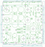
I worry about your proposed layout. 4 off KT88 on 2.5" centres, minimum recommended is 4". If you have cooling fans then you may get away with it, else you need a larger board or take the output tubes off teh board and chassis mount the tube sockets.
Cheers,
Ian
Cheers,
Ian
Ian, now that you mention it, the Audio Research people were horrible about that as well.
Positioning the tubes 4 inches apart will require a bigger chassis area, thus dictating monoblock construction. Audio Research probably did not want 30x18 inch chassis for a stereo setup. That would totally be impracticable for a living-room entertainment center.
Audio Research Reference 150 power amplifier | Stereophile.com
Audio research at 12k, seems a bit pricy, but I guess it's all relative. My question on the tube spacing is that something that I should really worry about if I'm running the amp at human listening level, ie, for 4" spacing on the tubes for full dissipation, can I assume a derating of continuous power but be ok it planned operation is not at full till.
$12k amp catching on fire, guess they should ship it with a halon system. BTW I solved the leaving the amp on problem somewhat by having them plugged into a GE mechanical timer 😉 Well doesn't really solve the problem, but helps some.
Thanks for spurning the ideas and raising issues.
Sandy
$12k amp catching on fire, guess they should ship it with a halon system. BTW I solved the leaving the amp on problem somewhat by having them plugged into a GE mechanical timer 😉 Well doesn't really solve the problem, but helps some.
Thanks for spurning the ideas and raising issues.
Sandy
I tried to talk that guy out of buying it but he has more money than he knows what to do with so he did not listen 🙁
I also seriously think that guy's wife married him for his money as they bicker and demonstrate all the classic signs of emotional immaturity. This tale just makes me work even harder at bettering myself in my field. Knowledge is power, not the rich bitch wanting the latest designer fad 😡
By the way, the spacing I believe is critical. Even at normal levels, on a push pull quad the heat can be felt 3 feet away. On summer days, the amplifiers alone raise the ambient temperature to where I need my air conditioner. That is a normal 27 degree summer day. Imagine the heat between the tubes. Yikes!
By the way, the spacing I believe is critical. Even at normal levels, on a push pull quad the heat can be felt 3 feet away. On summer days, the amplifiers alone raise the ambient temperature to where I need my air conditioner. That is a normal 27 degree summer day. Imagine the heat between the tubes. Yikes!
Last edited:
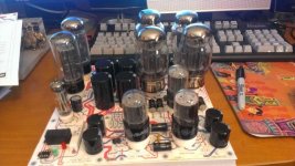
Just an example of a PCB based 6L6 family PP amp.. PCB with electrolytics on the bottom side away from the tube heat works just fine. Top plate is just warm to touch after 4hrs....
For a PPP amp, it may be best from a PCB design stand point to have the output tubes off of the PCB and have the PCB as the driver circuit, bias control and power supply filtering. That would reduce the size, wire it to the output tube sockets similar to the Dynaco designs.
For a PPP amp, it may be best from a PCB design stand point to have the output tubes off of the PCB and have the PCB as the driver circuit, bias control and power supply filtering. That would reduce the size, wire it to the output tube sockets similar to the Dynaco designs.
Attachments
Cool! I like tinkering with values too 😉
I totally get the inrush limiter (I've got a very active thread going regarding the best way to do this. Very informative. link). But why would you want to warm up the tubes completely before applying HT?? It will only stress the PSU.
Lookd at the thread and went back to revisit some of the 'Guesses' that I made, and they were all wrong 😉
Did some more work on the power supply designer (duncan amps) and came up with a better shot for the resistor, more like 5-10k depending on the where the relay will be OK switch it out of circuit. The relay is rated 350 volts DC into resistive load, but not sure how that may relate to switching with a capacitive load it it matters. Would like to see the caps charged to 350V or more when it overrides the resistor (nominal 500V supply).
The time constant for the delay is also a bit tricky. If you have it too long (to charge the caps more and reduce voltage across the resistor) you start getting into where the tubes are drawing significant current and that's not good for the relay and resistor. Also depending on the rectifier type silicon (Fast start), 5U4 (Medium start), or GZ34 (slower) the delay may be a problem for tube rectifiers if they come up slow as well as the rest of the tubes start drawing current but not enough time to charge the caps. This is all a guess, but in looking at the PSU Designer you can see a curve where you have a high enough charge and time delay works OK so the resistor doesn't blow due to heat.
That was the last part I looked at (and in the mentioned thread too) that the resistor will have to be a fair sized wattage at 10K, even more at 5K. I Have on the board a spot for a 10-14W wire wound and will add a second set of pads for an additional one in parallel if peak start up current is a problem with heat or resistor reliability. Dissipation with a 10K was in the 25 Watt range peak, 10+ watt resistor _may_ work if in circuit for a few seconds, but the extra resistor would be available if a problem. The 5K resistor may be better but again, may need to use 2 10+ watt resistor to support the inrush current and heat.
Will just have to give them a try and see how it works heat wise and the life of the relay.
Sandy
25 watt resistors?
That design can be made so much more efficient.
Peak wattage needed for a 10K resistor would be 25 watts, and I'll bet a 10 watt will be fine. That's a 2 dollar part. If not, toss in a second one for another 2 bucks. Are you worried about cost? It seems like a simple solution to me, and it's 99% out of circuit so nothing to worry about after it's up and running.
25 Watts would be the size needed for a 10k at 500v if a short on the other end of the resistor for total dissipation. The charge of the cap decreased this in a couple of seconds to much lower value then its out of circuit before it's toasted. Am I 100% sure it will work? No, but seems like it would if the peak does not toast the resistor. Am I confidant 2x 10watt resistors would work, yes, net cost 4 bucks, simple design.
Here's the worst case, I remove the relay, jumper the resistor and just turn the amp on.
I think this is just a matter of finding the right resistor value and it's all good, really doesn't seem to me to need to be more complicated then that. As soon as I get a board done, will report on this part of the amp.
Sandy
I always find resistive divider values through trial and error. Start with something that will deliver a ballpark value. A simulation is an OK approximation. You may have to keep a stock of large resistors on hand or use a huge rheostat. I like the rheostat idea. It will be expensive but it is worth it for a piece of test equipment.
Hi, SandyG,
Very nice, good looking assembly
I have a couple of notes (from my past experience with Williamson type amplifiers):
1) Cathode followers are not necessary. They serve no purpose but add additional pole. Better to use parallel 6SN7 in push-pull driver of output stage (V5 on your schematic), as it have been done in 400W RCA Williamson amplifier.
2) HF stabilization RC network between anode and grid#2 (100pF + 1K) - is it really necessary? Disconnect NFB, and load your amplifier at full power at 20, 100, 2,000, 10,000, 15,000 and 20,000 Hz, then repeat this procedure with GNFB on.
If there is no oscillation of UL output stage, these networks can be removed. Or you can try to measure leakage inductance of your output transformer. If its below 8mH Williamson most likely won't need it.
3) You can tune up input stage and concertina phase splitter according to article "Improved Williamson Amplifier" for minimum distortions. Google for it, it is available from many sites.
4) If you encounter problem with motorboating, shunt coupling capacitors leading to output stage with 1M resistors, as advised in article "Modernize your Williamson Amplifier" by David Hafler. Raise your BIAS voltage to the maximum level before that !!!
5) NFB fixed resistor should be replaced with trim pot + on/off during testing/debugging.
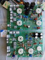
6) Williamson is quite tricky in terms of stability (which had to be checked at different frequencies and output levels), so it is more convenient to make test build on breadboard. Like the one shown below.
Very nice, good looking assembly
I have a couple of notes (from my past experience with Williamson type amplifiers):
1) Cathode followers are not necessary. They serve no purpose but add additional pole. Better to use parallel 6SN7 in push-pull driver of output stage (V5 on your schematic), as it have been done in 400W RCA Williamson amplifier.
2) HF stabilization RC network between anode and grid#2 (100pF + 1K) - is it really necessary? Disconnect NFB, and load your amplifier at full power at 20, 100, 2,000, 10,000, 15,000 and 20,000 Hz, then repeat this procedure with GNFB on.
If there is no oscillation of UL output stage, these networks can be removed. Or you can try to measure leakage inductance of your output transformer. If its below 8mH Williamson most likely won't need it.
3) You can tune up input stage and concertina phase splitter according to article "Improved Williamson Amplifier" for minimum distortions. Google for it, it is available from many sites.
4) If you encounter problem with motorboating, shunt coupling capacitors leading to output stage with 1M resistors, as advised in article "Modernize your Williamson Amplifier" by David Hafler. Raise your BIAS voltage to the maximum level before that !!!
5) NFB fixed resistor should be replaced with trim pot + on/off during testing/debugging.
6) Williamson is quite tricky in terms of stability (which had to be checked at different frequencies and output levels), so it is more convenient to make test build on breadboard. Like the one shown below.
Attachments
- Status
- Not open for further replies.
- Home
- Amplifiers
- Tubes / Valves
- EZ125 Quad KT88 Project