Thanks, working on it 🙂
Thanks for the pointers, the boards are in process now so can't make too much drastic changes.
Note some of the values are TBD still, so using a trimpot for testing the feedback is a good idea, as will be figuring out correct bias values for the input / driver of the amplifier.
1. Too late on this one, board are being made will see how it works. I have seen a few amps that use this and said what the heck, I'll give it a try. I have seen similar circuits driving an octet of KT88 and seemed like worth giving it a spin to see how it sounds.
2. The snubber circuit is a pcb stuffing option, I put it in the circuit as I had seen comments that in paralled tubed output stages it might be something that is needed. Will build the test unit without it and see if it is stable. Hopefully it will be, but have space on the board for the parts just in case 🙂
3. Yes, I think this is a good idea. Values are 'Get me going baseline' will be playing with these once things are up and running. I'll bug you for some pointers.
4. Good to know if I run into a problem!
5. Yes!
6. Those tube breadboard look very nice, but what would I do with the expensive PCB software! My idea with just doing the PCB is to design it with a circuit that is pretty generic and use good layout so I can hopefully have something close to working with just part value changes. I have been lucky on the last 2 amps (EZ10, EZ260). This amp is more complicated so hopefully I won't have to attack the completed PCB with the knife and dremel tool to make changes.
Thanks again for the pointers, I think these all will be useful as the first one gets built. I'll be posting progress as I get things rolling!!
Sandy
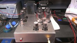
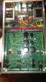
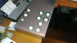
Test amp is built and running. At first I thought it was unstable, and turned it off and went to sleep. Then the next day woke up and forgot that it had the same odd behavior as another amp I built but has the the screen/plates flip/flopped so it changed them around and it worked!
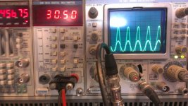
Amp is very clean and stable with no signs of waveform ugly across the audio spectrum. Begins to flattop at about 116 watts with solid state rectifiers and about 80 watts with a pair of old 5U4's.
This is with just guessing at some of the part values for the 6SN7 stages, and I'm sure their are some that would require changes between the voltage drop of the tube vs. the SS rectifier.
Need to get voltage readings and start working on the 6SN7's operating points...
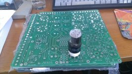
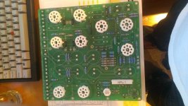
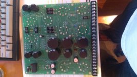
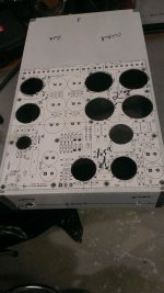
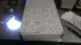
Pics below of some of the build.
Amp is very clean and stable with no signs of waveform ugly across the audio spectrum. Begins to flattop at about 116 watts with solid state rectifiers and about 80 watts with a pair of old 5U4's.
This is with just guessing at some of the part values for the 6SN7 stages, and I'm sure their are some that would require changes between the voltage drop of the tube vs. the SS rectifier.
Need to get voltage readings and start working on the 6SN7's operating points...
Pics below of some of the build.
Attachments
The amp definitely needs some refinement.
On my PPP amp, I obtain around 130 watts RMS at 0.25% THD at 1k. Distortion rises to 0.65% at 10k, and higher at 20k. There is a similar pattern at lower frequencies with the transformer I have.
Are you looking for undistorted power at 120 watts? What is the power goal here?
On my PPP amp, I obtain around 130 watts RMS at 0.25% THD at 1k. Distortion rises to 0.65% at 10k, and higher at 20k. There is a similar pattern at lower frequencies with the transformer I have.
Are you looking for undistorted power at 120 watts? What is the power goal here?
Yeah, I think it has a bit more to give. Would be nice to clip the 125 Watt mark 🙂 But it makes what it makes!
Kingneb - What was the B+ to your KT88's? I'm seeing right about 505 at idle (with bias in the range of 40 ma). I have to change one of the resistors in the bias circuit as I can't move it over about the 40ma mark due to one of the dropping resistors being too small, but for safe testing it works but need a bit more adjustment.
Will get some voltage reading hopefully tonight.
One thing I did measure was the with the 10K soft start resistor that the relay cuts out after startup it looked pretty close in value. With about 11 seconds on the relay delay the voltage comes up to about 300 vdc with the solid state rectifiers. So the relay is switching 200vdc.
I could make the voltage come up faster but in looking at the voltage on the 450v 56uf cap that is on the cathode follower it briefly clicks about 469v then quickly settles to about 434v which is OK. I think if I change the resistor from 10K to a lesser value it doesn't give enough time for 'things' to start drawing power and keep the 450v caps in a safe area.
Optimally might just make the delay a bit longer and that will keep things well below limits. Didn't see any heating issues with the 10w 10k resistor either.
More to come...
Sandy
- I am running 550 volts on my KT88/KT90 tubes.
- A KT88 should be biased optimally, at 500 volts B+, for 60mA for 30 watts static plate dissipation.
- Keep in mind the peak ripple voltage and cap ratings.
- For refinement, adjust driver B+ voltages and resistors for optimum linear operation.
- A KT88 should be biased optimally, at 500 volts B+, for 60mA for 30 watts static plate dissipation.
- Keep in mind the peak ripple voltage and cap ratings.
- For refinement, adjust driver B+ voltages and resistors for optimum linear operation.
Thanks, will update the bias circuit and get some voltage reading hopefully tonight or tomorrow.
I think the ~50vdc lower difference in B+ will account for the lower power I'm seeing. What secondary voltage (AC) on your transformer are you running (425-430vac)?
I did find some 500v 68uf caps at Digikey and will likely use those for the that part of the circuit for a bit more voltage headroom on start up.
I'm not sure what you mean by "peak ripple voltage", but if it matters these caps are past the main filters (pair of series connected 450v) so it's pretty clean DC at that point, but again not sure I understand.
Thanks for the tips too!
Sandy
For 120-130 watts I recommend you use 470uF of net capacitance (33uF before and the rest after the choke) since you are using optional 5U4s. 5U4s cannot take the inrush current beating of large caps. The large capacitance is so the power supply can recover from bass transients. There is a formula for the minimum power supply capacitance that can be found here:
tubes
I also recommend you place two caps in series with bleeder resistors across them. This halves the effective capacity but doubles the working voltage. This allows for cheaper and bigger cap use.
tubes
I also recommend you place two caps in series with bleeder resistors across them. This halves the effective capacity but doubles the working voltage. This allows for cheaper and bigger cap use.
Thanks for the link.
I'm running 380uf total right now on the main B+, then each 6sn7 tube has a 56uf buffer. I have currently reduced the first caps off the rectifiers to a total of 50uf to support the 5u4's but with the solid state it would have been a total of 495uf .
Take a look at the schematics on the very first post (A few values have changed since the post), it will explain a lot of what I did on this amp and power supply. Note that it can be built in a few different configurations, ie, if you don't want to use the chokes, don't, solid state or tube for rectifiers, you pick and then build as desired. Tried to make it so I could try different configurations and see how I like the sound.
Sandy
Last edited:
Updated schematics (Minor changes) but the amp schematic has the measured voltages.
These were taken at a bias of about 50ma/tube.
Now to do some calculations...
These were taken at a bias of about 50ma/tube.
Now to do some calculations...
Attachments
Check the 5U4's for flashes on turn on/B+ power up. I have a feeling 50uF is pushing it too far.
I have done a bit more capacitance on the 5U4GB's on another amp without the soft start and have not run into any issues with either JJ's or old 5U4GB's.
While I do not have the series resistor that most all of the 5U4GB datasheets recommend, they are recommending max 40uf for a single rectifier tube. I'm running 50uf with 2 tubes which is better, but likely still not in spec since I do not have a series resistor out of the tube to the caps and running a lot of voltage. I do have a place on the PCB for the resistor if I needed it just in case, but have not run into problems yet, and have a box of good used tubes.
Sandy
SandyG,
Congratulations on your development! (only noticed this now ....)
I happen to be busy with a similar venture, so can associate with most of the remarks. If I may: I use 4 x 6L6GC in a similar vein but with cathode feedback (a la Quad II style). My maximum output is 115W, with 550V on anodes and 500V regulated on screens and the rest of the amplifier. The topology is also similar to yours but with a pentode input (ECF80, triode as phase splitter) and a E182CC driver - the output configuration needs quite a grid signal swing.
My observations would be as follows (but none of it meant as criticism or suggestions to change at this late stage).
1. I would definitely advise a delayed application of h.t. The jury seems to be out still on cathode stripping, but I am not taking a chance. Also, for one thing: With h.t. on and before cathode heat-up, the phase splitter has the full voltage between grid and cathode - is that OK? Also we do not know that both cathodes of the 6SN7 will heat up at exactly the same rate.
I do switch with a (small) relay, but into a choke-input filter, so no current rush-in and much danger of contact welding. The voltage between contacts could however be close to 800V. I bent the contact gap slightly further open, and tested that they could stand >2KV before flashing over.
2. The presence and values of C18-R20: That depends on the OPT characteristics (together with the KT88s). One can best determine that with a square wave followed by a frequency sweep in the 50kHz - 200kHz region, before NFB and after. I have not been able to do without them, values depending.
3. The KT88 grid drive: Cathode followers not necessarily superfluous; one must be careful of distortion feeding from a 47K anode load into a 100K capacitive-coupled next-stage resistance. (I chickened out and fed into an equivalent 410K next-stage resistance, but with active servo correction for grid current effect applied. But that is another story.)
4. Small handy hint (but too late now!): If the bias pots could be wired so that on dirty or open contact the bias goes high (negatively) instead of low as with you, it might save a tube.
5. LF stability: Yes, it was a problem with the Williamson, but then also because of the low power supply caps (one tends to ignore them; they are also poles!). I have 5 poles at l.f. but the stability is in order with the choice of proper time constants. [My amplifier goes to 10 Hz (-3dB), and has been checked to 0,1 Hz for peaks indicative of l.f. problems. Spice is your friend here.]
6. As done by you: Definitely filter caps in series. Also not too large divider resistors; electrolytics are notorious for spreads in capacity unless you select, and one might charge rather faster than the other, leaving a momentary peak there.
Otherwise, you are outdoing me in output capacity! Again, none of the above meant as criticism, and thanks for patience in reading this.
Good luck! (and do beware of touching where you should not; I once had the 550V across my hand 😱 - not nice.)
Thanks for the tips John.
I have not played with much yet, but on initial testing the square wave looked pretty good, over the audio range. Much of the circuit is not mine, it was lifted from a couple of older amps and combined into one. From initial testing the amp seems very stable, I have to clean up some of the voltages to the 6SN7's as they seem to work OK but I think not close to being even good.
I do have the HV turn delay and I watch the variac's watt meter when it hits and it jumps a bit more then I like. I may reduce the value of 'bypass' resistor from 10k for a bit less load on the relay. I think the voltage it's switching is OK now, but would be a bit better if lower. The 6SN7's get warmed up quickly and start drawing current at the end of the 11 seconds the relay is open, then it takes another 10+ before the KT88's draw power. I'm not at all worried about cathode striping, just trying to avoid jolting the system on power up. One issue is keeping the first 6SN7's buffer at a reasonable voltage until things start drawing some current. I will be changing that part's value to 500V when I order some additional parts. That will also help as I'll also likely change the value of the main power transformer up to maybe 425VAC when I order the final version.
Yes on the bias resistor changes 😉 If I do another set of boards that's an easy fix.
Still learning as I'm going, but good advice here and it's all very much a learning experience!
Sandy
About to start looking at the load lines, which I can see might be way off from what I here people like to run for the 6SN7GTB's, but not sure. I have seen comments that people like to run them from 6-8ma on the input. I'll show my work just in case I'm doing it all wrong.
The formula...
(Ebb - Vplate) / Rplate = Iplate
Input
167-87.1 / 47000 = 1.7ma (might be low)
Phase Splitter
351-261.4 / 22000 = 4.0ma (might be OK)
First Driver
410-138.8 / 220000 = 1.2ma (each half, might be low)
Cathode Follower
428-151.1 / 47000 = 5.9ma (each half, might be on the edge of high with 2.5 watts each half)
Anyone have some good guidelines where the plate current might be better optimized?
That being said waveforms look very clean across the audio spectrum as well, nothing out of place. Will have to do a bit more testing to see but it looked like a clean waveform at full power and at a few other power test points.
Sandy
Johan, the jury has come to a conclusion many years ago. There has been scientific article after article about stripping. For indirectly heated cathodes, cathode stripping is a myth. Nothing more than a remnant from the directly heated tube era. Preheating the tubes before HT is applied can in some cases actually cause more harm than good. Think PSU stress when HT is applies with fully heated KT88's for example.1. I would definitely advise a delayed application of h.t. The jury seems to be out still on cathode stripping, but I am not taking a chance. Also, for one thing: With h.t. on and before cathode heat-up, the phase splitter has the full voltage between grid and cathode - is that OK? Also we do not know that both cathodes of the 6SN7 will heat up at exactly the same rate.
Last edited:
I'm running 50uf with 2 tubes which is better, but likely still not in spec since I do not have a series resistor out of the tube to the caps and running a lot of voltage.
I assume that the diodes D1-4 shown in your schematic are not present... (D2 and D3 would only be needed if you did not have a centre-tapped transformer - As drawn they will blow the centre-tap fuse.) Or is there no centre-tap? In which case D2 and D3 form the lower half of a bridge?
Regarding the capacitor value, 50uF is probably safe, but since the two rectifier valves (as drawn) operate on opposite phases of the AC supply, the valves are not in parallel, and each may see the full surge current into the capacitors.
Provided that the valve's voltage ratings allow, you could swap one of the anodes on one rectifier with one of the anodes on the other. Then both valves would operate on both halves of the mains cycle and the cathode currents would be shared between them.
On the plus side, you can take the DC resistance of the transformer secondary into account and regard that as part of any current limiting resistance that might be needed.
Just a thought...
Les.
Last edited:
12E1 -
Thanks for the info. The Diodes are only used depending on how and what type of rectification is desired. So you can use bridge, full wave semiconductor or tube depending on what you stuff into the PCB.
The datasheet for the 5U4GB shows a 40uf input cap max (of course with appropriate limiting resistors), but my thinking was that was for a single tube operating as a bridge. Since I'm running 2 tubes with each of them acting as a single paralled diode, I would expect to have the same capability as criss-cross wiring the diodes in the 2 tubes. My thinking is that the 5U4 is a tube with 2 independent diodes does it matter if in the same envelope or not with respect to current capability?
Practically it seems to work OK, I have another amp with a similar set up at a bit lower voltage and a bit higher first cap value and they are running some old 5U4GB's and have been running for a good amount of time and that amp has no soft start. I'll say that it's not enough to concluded it works reliably, but I have a box of old 5U4GB's so if it's a short life maker of the tubes I have a few spares 🙂
Now to figure out good operating points on the 6SN7's...
Sandy
It just depends what the limiting factors are that lead to the setting of the datasheet limits. I was thinking cathode current, but now that I think about it some more I see that it's not as simple as that since each anode will conduct to a separate part of the cathode surface. Maybe it makes no difference. 😕The datasheet for the 5U4GB shows a 40uf input cap max (of course with appropriate limiting resistors), but my thinking was that was for a single tube operating as a bridge. Since I'm running 2 tubes with each of them acting as a single paralled diode, I would expect to have the same capability as criss-cross wiring the diodes in the 2 tubes. My thinking is that the 5U4 is a tube with 2 independent diodes does it matter if in the same envelope or not with respect to current capability?
I think that I would cross the anodes to share the currents as I described, but then I would also split the capacitors and filters on a per channel basis, thus maximising the channel separation while only using a single transformer. However, that's a major change from where you are now, so maybe it's best to take the view "if it ain't broke, don't fix it" and leave things as they are.
- Status
- Not open for further replies.
- Home
- Amplifiers
- Tubes / Valves
- EZ125 Quad KT88 Project