Tommus,
Sound attenuation losses over long distance in the great outdoors are the sum of geometric spreading, atmospheric absorption, reflection or absorption from various surfaces, refraction caused by temperature gradients, diffraction, and other effects.
Environmental effects certainly do affect the propagation of sound over long distance, and the wider the pattern of the source speaker, the more the potential for destructive interference patterns, loss of coherence and SPL (sound pressure level) due to all the above.
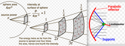
While the most narrow horn speaker is still radiating in a portion of sphere, loosing at minimum 6dB with each doubling of distance, a parabolic dish reflector/projector in theory can produce a plane wave, which would have no divergence over distance- a two meter diameter source would project a beam that would still only be two meters in diameter at 10,000 meters away, considerably reducing most of the outdoor effects.
In practice, it appears that the best results using a parabolic projector are about a 10 degree beamwidth at distances greater than 100 meters.
In practice, in the speech range, using a large 1.5-2 meter parabolic projector about half the loss per doubling of distance as using a point source can be achieved.
In post # 31, I gave some real world comparative examples, losses were more than double those predicted from the inverse distance law (-6 dB per doubling of distance). The 13 x 13 degree horn’s output fell in to the noise floor at 500 feet (154 meters) while at around 122dB at one meter.
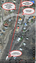
Another example from that test era was using a Tannoy PBM 6.5 (a 6.5” 88 dB sensitivity two-way) as the speaker with a 6’ parabolic projector. Due to environmental effects, on a good day, I’d estimate that speaker could not be heard much past 300 feet/100 meters without the reflector.
However, with the reflector, I could still easily hear the lyrics of music at over 850 feet/250 meters. A map of the test area below.
The projector was aligned with Firehouse Lane, and was at about 1 foot above ground level, pointed towards the horizon. Walking down the hill from the location, the output was remarkably consistent, though when near the Firehouse the reflection from it’s south side could be heard as loud as the source.
Turning left (West) on Highway 14, sound dropped out in the acoustic “shadow” of the building just south, returned, then dropped out again when out of the (roughly) 10 degree projection pattern.
The terrain in the available coverage area was very rough, I turned back somewhere past 800 feet/250 meters, but have no doubt that I could have gone twice that distance and still have heard the lyrics. That said, being 1999, using a CD player, I had already played an entire album by the time I returned from that coverage walk 😉
Art
Sound attenuation losses over long distance in the great outdoors are the sum of geometric spreading, atmospheric absorption, reflection or absorption from various surfaces, refraction caused by temperature gradients, diffraction, and other effects.
Environmental effects certainly do affect the propagation of sound over long distance, and the wider the pattern of the source speaker, the more the potential for destructive interference patterns, loss of coherence and SPL (sound pressure level) due to all the above.
While the most narrow horn speaker is still radiating in a portion of sphere, loosing at minimum 6dB with each doubling of distance, a parabolic dish reflector/projector in theory can produce a plane wave, which would have no divergence over distance- a two meter diameter source would project a beam that would still only be two meters in diameter at 10,000 meters away, considerably reducing most of the outdoor effects.
In practice, it appears that the best results using a parabolic projector are about a 10 degree beamwidth at distances greater than 100 meters.
In practice, in the speech range, using a large 1.5-2 meter parabolic projector about half the loss per doubling of distance as using a point source can be achieved.
In post # 31, I gave some real world comparative examples, losses were more than double those predicted from the inverse distance law (-6 dB per doubling of distance). The 13 x 13 degree horn’s output fell in to the noise floor at 500 feet (154 meters) while at around 122dB at one meter.
Another example from that test era was using a Tannoy PBM 6.5 (a 6.5” 88 dB sensitivity two-way) as the speaker with a 6’ parabolic projector. Due to environmental effects, on a good day, I’d estimate that speaker could not be heard much past 300 feet/100 meters without the reflector.
However, with the reflector, I could still easily hear the lyrics of music at over 850 feet/250 meters. A map of the test area below.
The projector was aligned with Firehouse Lane, and was at about 1 foot above ground level, pointed towards the horizon. Walking down the hill from the location, the output was remarkably consistent, though when near the Firehouse the reflection from it’s south side could be heard as loud as the source.
Turning left (West) on Highway 14, sound dropped out in the acoustic “shadow” of the building just south, returned, then dropped out again when out of the (roughly) 10 degree projection pattern.
The terrain in the available coverage area was very rough, I turned back somewhere past 800 feet/250 meters, but have no doubt that I could have gone twice that distance and still have heard the lyrics. That said, being 1999, using a CD player, I had already played an entire album by the time I returned from that coverage walk 😉
Art
Attachments
Last edited:
An old Ka band antenna might make a good reflector base. I bet someone would let you take one for free.
Only way I know to really focus at a point is the ultrasonic modulation method. Not simple DIY and at high levels, possibly dangerous.
Only way I know to really focus at a point is the ultrasonic modulation method. Not simple DIY and at high levels, possibly dangerous.
You mean C band, not Ka. The Ka and Ku dishes are small, and the C-band ones huge (8 feet). Useless for the intended purposes today, and a nuisance for the owner to get rid of.

Freddi,
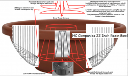
That HC Companies 22" resin bowl might be close enough to a hyperbolic curve to work reasonably well.
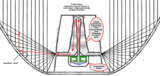
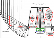
The sketch below shows a design I just made based on Curt Graber's Hyperspike designs, using the resin bowl.
This type of device, if attention to detail is superb, can approach a 3dB loss per doubling of distance in the upper range, though air attenuation kills VHF at long distances.
Using typical PA drivers, there isn't much response above 6kHz, so that detail is not of much concern for the normal (or abnormal..) use of such a device.
I'd expect it's pattern control to diverge from the plane wave effect below around 500Hz, but the low frequency range could extend to around 200 Hz at a reduced level, response falling to the usual 6db per doubling of distance. In effect, the unit would sound progressively "thinner" at distance.
It could use most any common re-entrant (folded) horn/driver combination exiting through a DIY 360 degree horn mouth. A pair of properly sized plastic plates, or a Smith type horn would suffice for that portion.
Art
That HC Companies 22" resin bowl might be close enough to a hyperbolic curve to work reasonably well.
The sketch below shows a design I just made based on Curt Graber's Hyperspike designs, using the resin bowl.
This type of device, if attention to detail is superb, can approach a 3dB loss per doubling of distance in the upper range, though air attenuation kills VHF at long distances.
Using typical PA drivers, there isn't much response above 6kHz, so that detail is not of much concern for the normal (or abnormal..) use of such a device.
I'd expect it's pattern control to diverge from the plane wave effect below around 500Hz, but the low frequency range could extend to around 200 Hz at a reduced level, response falling to the usual 6db per doubling of distance. In effect, the unit would sound progressively "thinner" at distance.
It could use most any common re-entrant (folded) horn/driver combination exiting through a DIY 360 degree horn mouth. A pair of properly sized plastic plates, or a Smith type horn would suffice for that portion.
Art
Attachments
Last edited:
That's absolutely amazing and if done well, should cover speech nicely. (It would be fab for Halloween)
What is your eyeball estimate of the re-entrant section's path length and moth area and diameter?
Would conical sections made of lap - joint cones be good enough? What besides soldered sheet metal might work? (some sheet plastic and glue?)
Perhaps the gentleman who wants a directional horn for a synth show could go this route.
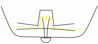
Does this rough addition to your sketch basically describe the re-entrant horn section?
What is your eyeball estimate of the re-entrant section's path length and moth area and diameter?
Would conical sections made of lap - joint cones be good enough? What besides soldered sheet metal might work? (some sheet plastic and glue?)
Perhaps the gentleman who wants a directional horn for a synth show could go this route.
Does this rough addition to your sketch basically describe the re-entrant horn section?
Attachments
The parabolic reflector is the best choice here as already posted. The speaker should be placed exactly in the focal point. The challenge is to make such a big parabolic reflector in 3D and to find the focal point.
The parabolic horn must have a large mouth diameter as otherwise if the wave length is in the range of the mouth diameter you get dispersion and the dispersion angle widens up which is not what was intended. The same holds for the conical horn where you would need a large mouth diameter to avoid dispersion.
The parabolic horn must have a large mouth diameter as otherwise if the wave length is in the range of the mouth diameter you get dispersion and the dispersion angle widens up which is not what was intended. The same holds for the conical horn where you would need a large mouth diameter to avoid dispersion.
Freddi,What is your eyeball estimate of the re-entrant section's path length and moth area and diameter?
Would conical sections made of lap - joint cones be good enough? What besides soldered sheet metal might work? (some sheet plastic and glue?)
Reviewing John Meyers, Curt Graber's and my own tests, it is apparent the hyperbolic projector will far outperform a parabolic projector of the same diameter at frequencies lower than 1000 Hz.
The HL 14 won’t go as low as a folded horn the same length.
High quality re-entrant PA horn/drivers are a complex, hard to DIY item, yet are a relatively cheap commodity item. I would not suggest trying to duplicate them using sheet metal or lap joints unless one was looking to spend a long time on construction.
Simply discard the horn "bell" of the re-entrant PA horn/driver, and make the rest. The central cone portion could be made from a pail with damping material added to eliminate resonance.
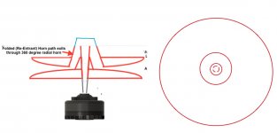
The radial portion of the horn placement and diameter are determined by the diameter and curve of the hyperbolic “bowl”.
The profile sketch below should give you a better idea of the geometry involved for the hyperbolic plane-wave projection.
Art
Attachments
Last edited:
thanks Art - I thought it might be long enough for the driver to mount "behind" the flat spot
roughly what would you say the horn path would be for this bowl?
Also, can a portion of a reflector like this be used to direct some junk out of a Karlson's front chamber?
roughly what would you say the horn path would be for this bowl?
Also, can a portion of a reflector like this be used to direct some junk out of a Karlson's front chamber?
Attachments
Freddi,
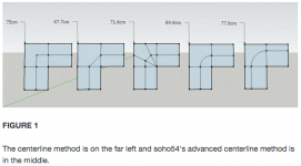
Not sure which horn or bowl you are now asking about, but estimates of a horn path using the "advanced centerline method" simulate close to measured results.
The Karlson front chamber reflections and resonances do a variety of different "junk" (or "enhancement") at different frequencies.
Can't see using a hyperbolic reflector inside it being of any "hi-fi" use.
Art
Attachments
Thanks Art
It was that 22" bowl, ans wondering if an HL14 horn and a couple of plastic plates would make the system.
It was that 22" bowl, ans wondering if an HL14 horn and a couple of plastic plates would make the system.
Freddi,
Reviewing John Meyers, Curt Graber's and my own tests, it is apparent the hyperbolic projector will far outperform a parabolic projector of the same diameter at frequencies lower than 1000 Hz.
The HL 14 won’t go as low as a folded horn the same length.
High quality re-entrant PA horn/drivers are a complex, hard to DIY item, yet are a relatively cheap commodity item. I would not suggest trying to duplicate them using sheet metal or lap joints unless one was looking to spend a long time on construction.
Simply discard the horn "bell" of the re-entrant PA horn/driver, and make the rest. The central cone portion could be made from a pail with damping material added to eliminate resonance.
The radial portion of the horn placement and diameter are determined by the diameter and curve of the hyperbolic “bowl”.
The profile sketch below should give you a better idea of the geometry involved for the hyperbolic plane-wave projection.
Art
I really like this idea, I was looking as Cassegrain structures, this approach would be more containing. The sketch is clear. One would use the existing gap at the base of the megaphone or is there any optimizing to be done in terms of the edge shape before heading into the hyperbolic dish?
Are there any discussions of the comparison of hyperbolic vs parabolic and lower frequency?
1) Not sure of what you mean by "the existing gap at the base of the megaphone", but the rough hyperbolic projector sketch is just the basic concept, optimization would be required for the specific drivers used and hyperbola diameter and depth.1)One would use the existing gap at the base of the megaphone or is there any optimizing to be done in terms of the edge shape before heading into the hyperbolic dish?
2)Are there any discussions of the comparison of hyperbolic vs parabolic and lower frequency?
The design also lends itself to the addition of multiple entry LF offset cone drivers in the radial horn, though would require a larger diameter than the 22" bowl example to fit cone drivers large enough to provide useful output, as neither the radial portion of the horn or hyperbolic projector provide much "horn gain".
2) In post #14 the link gives more details to my previous hyperbolic and parabolic projectors, as well as those that inspired them.
The hyperbolic arrangement is better in terms of directing lower frequencies as a plane wave than a parabolic dish of a given diameter, the extra depth reduces side spill considerably.
Using horn/driver (or cone loudspeakers) directed back into a parabolic reflector, much of the HF energy is wasted in reflections back into the horn/driver, much of the LF is wasted as side lobes and out of phase forward energy.
The hyperbolic arrangement minimizes both those deficits by a considerable margin.
Art
Last edited:
Art, read up on #14, thank you. Followed the Graber patents, great seed of information.
This is how I envision replacing the outer shell of a commercial megaphone with a parabolic guide for a fast test of a portable "projector".

Based on Art's sketch, these are the calculated angles, they leave parallel and equal length.

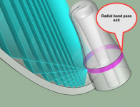
 The gap noted here in pink. If that exit shape has an ideal form. I assume sticking with the "as manufactured" shape, and locating it at the focus point of the parabola.
This is how I envision replacing the outer shell of a commercial megaphone with a parabolic guide for a fast test of a portable "projector".
Based on Art's sketch, these are the calculated angles, they leave parallel and equal length.
Not sure of what you mean by "the existing gap at the base of the megaphone"
The gap noted here in pink. If that exit shape has an ideal form. I assume sticking with the "as manufactured" shape, and locating it at the focus point of the parabola.Where would the LF drivers fit into a solution like this?The design also lends itself to the addition of multiple entry LF offset cone drivers in the radial horn, though would require a larger diameter than the 22" bowl example to fit cone drivers large enough to provide useful output, as neither the radial portion of the horn or hyperbolic projector provide much "horn gain".
Art
Stratotron,The gap noted here in pink. If that exit shape has an ideal form. I assume sticking with the "as manufactured" shape, and locating it at the focus point of the parabola.
Where would the LF drivers fit into a solution like this?
As depicted, the gap noted in pink would become a radial band pass resonant exit, the output would be "interesting".
The exit of the exponential HF driver horn must be directed into the hyperbola, the "U" shaped curve of the last turn in a "as manufactured" shape should be converted to a curved "L".
Your depiction using a typical (under 1" exit) PA driver results in a small mouth exit that will become near omnidirectional around 500 Hz.
Larger diameters afford more possibilities for LF.
Art
Attachments

The exit of the exponential HF driver horn must be directed into the hyperbola, the "U" shaped curve of the last turn in a "as manufactured" shape should be converted to a curved "L".
Art, thanks for that clarity. I'll draft up my understanding of that.


I'm very intrigued by this Graber illustration from a 2013 application. Two drivers face to face with a guide sandwiched between and the pressure exiting the rim. I wonder if the diagram you have shown could have a single large driver underneath it all with the same ring spill into the L-shaped channel. Will draft that as well.

note the similarity to this 1924 design 🙂 cross section made radial.
- Home
- Loudspeakers
- Multi-Way
- extremely narrow directivity speaker design