I'm sorry, but why would you want to combine a inherently distorting tube front end with a power stage that effectively lacks any? That's like putting a F1 engine into a small family car.
Member
Joined 2009
Paid Member
Don't be sorry, we all have our vices !
If this project gets off the ground for me, I'd like to have an OPS that is truly blameless, a 'perfect' output stage where the overall performance of the amplifier is due to the front end. It allows me to explore some ideas - in the spirit of DIY!
I am also thinking of using a Class D amplifier for the OPS instead, most likely a UCD based design. However, I have no experience with Class D so this might be putting too many unknowns into the design at the same time. A perfect Class A stage could be the better approach.
So, you see, that is exactly the question - I actually want to put a F1 engine into my family car.
Mind you, if this gets to the stage of a pcb layout I'll probably include an alternative footprint for a SS voltage amp front end.
Do I have permission ? 🙂
Last edited:
We all have our vices.
If this project gets off the ground for me, I'd like to have an OPS that is truly blameless, a 'perfect' output stage where the overall performance of the amplifier is due to the front end. It allows me to explore some ideas - in the spirit of DIY!
The end result is likely to be a new pcb, with footprint for two different front end designs. One will be a tube, the other will be a SS voltage amp.
Do I have permission ? 🙂
Go for it, the design cannot be used commercially but if you want to tinker and play with it, by all means 😀
Member
Joined 2009
Paid Member
First step is to understand the output stage. Do you by any chance have a ".asc" file you can post ?
p.s. I noticed that I edited my post whilst you were quoting it, funny to see the mismatch after the fact.
p.s. I noticed that I edited my post whilst you were quoting it, funny to see the mismatch after the fact.
I also would not use a tube with ExA. Why? Colorizers are not needed. It needs as transparent preamplifier as possible, to show its best. I have a preamplifier based on AD797 + BUF634T in its feedback loop. No measurable distortion above -130dBr, which is my measurement limit.
Member
Joined 2009
Paid Member
Well, my goal is not to build a copy of what you have made - as perfect as it is - I want to find some part of the road that is less traveled where I can make my own footprints even if they are less pretty.
If there is a strong sense that it would be some kind of blasphemy to use this OPS - I will look elsewhere.
If there is a strong sense that it would be some kind of blasphemy to use this OPS - I will look elsewhere.
I also would not use a tube with ExA. Why? Colorizers are not needed. It needs as transparent preamplifier as possible, to show its best. I have a preamplifier based on AD797 + BUF634T in its feedback loop. No measurable distortion above -130dBr, which is my measurement limit.
Pavel,
Would you mind posting the schematic of your preamp? It sounds interesting!
Member
Joined 2009
Paid Member
These BUF634 parts are pretty interesting - about $12 from Digikey in TO-220, good for driving headphones with what looks like wide bandwidth, good slew rate; PSRR tops out at 80dB but if used in a compound amplifier you get lots more rail rejection.
Last edited:
Pavel,
Would you mind posting the schematic of your preamp? It sounds interesting!
Can I respectfully request we stay on-topic? I.e. discuss the ExtremA design. I would suggest using PM to contact Pavel with such requests.
Harmonic structure at listening level: 2nd at -122dB, 3rd at -119dB, there is nothing to talk about like distortion. Absolutely smooth step response, output stage is still very good at 1MHz, this amplifier is much better than my class A 12 years ago was. This is a "Sound Reference", to me. No flaws. Perfect from bass to treble. It has an ability to bring the specific concert hall acoustics and reverberations better than anything else I have ever heard.
Thanks PMA. I tried similar OPS in class A and it sounded perfect but I have no distortion measuring equipment...
Last edited:
I also would not use a tube with ExA. Why? Colorizers are not needed. It needs as transparent preamplifier as possible, to show its best. I have a preamplifier based on AD797 + BUF634T in its feedback loop. No measurable distortion above -130dBr, which is my measurement limit.
The truth is that as a front end, amplifying low level signals, tubes are excellent. Many SS devices require feedback (which is fine when used properly), where as a tube can reach reasonable levels with out. Remove your predispositions in everything and select what works best. Tubes creating "color" is for guitar amps and poorly designed stereo applications. I am not saying that tubes are the answer, only that they need to be tried and tested, anything else is nothing but conjecture.
Last edited:
I have had experience with all kinds of amplifying devices since the end of the sixties. No prejudice.
The truth is that as a front end, amplifying low level signals, tubes are excellent. Many SS devices require feedback (which is fine when used properly), where as a tube can reach reasonable levels with out. Remove your predispositions in everything and select what works best. Tubes creating "color" is for guitar amps and poorly designed stereo applications. I am not saying that tubes are the answer, only that they need to be tried and tested, anything else is nothing but conjecture.
The difference between distortion of the ExtremA OPS and any tube front end is several magnitudes, so you effectively cripple the OPS and nullify all the design work that has gone into creating such a low distortion OPS.
How about we stick to the ExtremA design discussed here and avoid discussion about all sorts of contraptions based on one's own preference? By all means start a new topic if you're looking to discuss alternative solutions.
Sander, looking at the OPS, it looks like the bias setting also doubles as an error correction á la Cordell/Hawksford. Is that correct?
Jan
Jan
Member
Joined 2009
Paid Member
How about we stick to the ExtremA design discussed here and avoid discussion about all sorts of contraptions based on one's own preference? By all means start a new topic if you're looking to discuss alternative solutions.
I think you're right. Any alternatives we might be interested in would simply be inferior, almost a slap in the face for this fine output stage, an unworthy transgression on its purity and perfectness by those without the vision and self-discipline to make the right choices and stick with the proper designs...

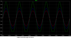
Results:
1628Hz, Vout = 7.42Vrms, auxiliary preamplifier only, THD = 0.00048%
1628Hz, Vout = 7.42Vrms, Rload = 6.8ohm, preamp + ExA output stage, THD = 0.0006%
Question is how the numbers would look if a 2nd pair of output devices would be added, 1st pair inside the FB loop and the 2nd couple outside.
(on my 2905's, I could use a bit more output stage quiescent current if used in a larger room than the current one)
Question is how the numbers would look if a 2nd pair of output devices would be added, 1st pair inside the FB loop and the 2nd couple outside.
In case of the ExA output stage, simulation is very close to the real world result. Interestingly enough, the real world result has been even better than the simulated distortion.
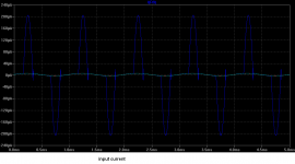
The output stage loads the preceding stage very lightly, as long as it stays in class A. We can speak about microamperes. This is dramatically, really dramatically changed at the moment when the output stage leaves class A.
This is probably not a direct answer to your question, but I know you can read between the lines very well.
Regarding the bridged operation, it always cancels even harmonics.
Not inferior by any means.
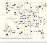
In fact , .23PPM @ 50W !!
I did "transgress" and used FET's 😱 . (below).
All works fine with the IRF's , except (speed). Unless you "slow" the
feedback path with either the input shunt or the B-C shunt at the FB
pair , you get ringing. 🙁
With the BJT's .... and If there is no "lust" for 300V/uS slew. This is a
perfect OPS.
The "Moskido" Class A is the same concept , but uses current FB to do the
same thing.
Stunning (error correction wise) !!!
OS
I think you're right. Any alternatives we might be interested in would simply be inferior, almost a slap in the face for this fine output stage, an unworthy transgression on its purity and perfectness by those without the vision and self-discipline to make the right choices and stick with the proper designs...
In fact , .23PPM @ 50W !!
I did "transgress" and used FET's 😱 . (below).
All works fine with the IRF's , except (speed). Unless you "slow" the
feedback path with either the input shunt or the B-C shunt at the FB
pair , you get ringing. 🙁
With the BJT's .... and If there is no "lust" for 300V/uS slew. This is a
perfect OPS.
The "Moskido" Class A is the same concept , but uses current FB to do the
same thing.
Stunning (error correction wise) !!!
OS
Attachments
- Status
- Not open for further replies.
- Home
- Amplifiers
- Solid State
- ExtremA, class-A strikes back?