@mikeB
I Have Finish Build Sym Headamps.... 😀
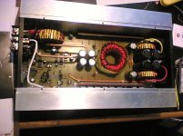
I Too lazy to make new pcb, so i modified my first test board for other channel.
I Use BD911/BD912 because I Only Have One MJE15030/MJE15031, I use 100pf wima Fkp, Ceramic 22 & 47pf, solen 4.7uF as input caps and Small Heatsink (I Must change with bigger heatsink because it's too hot)
I only Use +13.3v 0 -13.3v (Regulated PSU With LM317/337)
R Accross R 1.2 Ohm 0.16v
DC Offset 2.7mV and 7.2 mV (I Need to match it again)
I don't Put Potentiometer at Input.
I Use Soundcard (Chaintech A7V-10) As input.
Headphone Grado SR-80 (impedance 32 Ohm)
sound too loud and I Must Set Soundcard Volume At 10%.
It's Have too many gain/ Power.
how to lower gain this headamps ?
I Have Finish Build Sym Headamps.... 😀
I Too lazy to make new pcb, so i modified my first test board for other channel.
I Use BD911/BD912 because I Only Have One MJE15030/MJE15031, I use 100pf wima Fkp, Ceramic 22 & 47pf, solen 4.7uF as input caps and Small Heatsink (I Must change with bigger heatsink because it's too hot)
I only Use +13.3v 0 -13.3v (Regulated PSU With LM317/337)
R Accross R 1.2 Ohm 0.16v
DC Offset 2.7mV and 7.2 mV (I Need to match it again)
I don't Put Potentiometer at Input.
I Use Soundcard (Chaintech A7V-10) As input.
Headphone Grado SR-80 (impedance 32 Ohm)
sound too loud and I Must Set Soundcard Volume At 10%.
It's Have too many gain/ Power.
how to lower gain this headamps ?
dytln_02 said:
sound too loud and I Must Set Soundcard Volume At 10%.
It's Have too many gain/ Power.
how to lower gain this headamps ?
That's what I already told you, look here:
http://www.diyaudio.com/forums/showthread.php?postid=935524#post935524
This amp is not suitable as a headphone amp, as you will not be able to make feedback freq. compensation for gains like 2 - 4.
You have to use divider at the output.
Ryssen said:Will a heatsink that´s 7x6x2 inch be enough for 2 channels?
Hi Ryssen, that sounds to small for 2 channels, but should be enough for a single channel.
dytln_02 said:
I don't Put Potentiometer at Input.
sound too loud and I Must Set Soundcard Volume At 10%.
It's Have too many gain/ Power.
how to lower gain this headamps ?
I will give you new values this evening. I didn't know that you will not use input pot.
PMA said:
This amp is not suitable as a headphone amp, as you will not be able to make feedback freq. compensation for gains like 2 - 4.
You have to use divider at the output.
Hi Pavel, that's no problem, i can adjust openloop gain anytime to keep feedback ratio constant. The headamp is already unity gain stable and by increasing degeneration more i can easily set any gain wanted without changing feedback. CL-gain was already dropped to 12, but obviously still too much.
You can see the numbers here:
http://www.diyaudio.com/forums/showthread.php?postid=942979#post942979
Mike
Hi Chris
It is a great idea. I have had many car amps and have always noted that the treble seems to fall off very rapidly after about 10kHz probably because the components used in them are of a cheaper quality.
I also feel that there is no need to bridge an amplifier into 4R or use 2 speakers per channel if the amplifier has enough power as
this just leads to more distortion.
I personally measured a 1kHz waveform before clipping at 120wrms/ch with Vin+ and Vin- set to 36.5V.
In my opinion 400w rms in a car is more than good enough for all except a few people.
The PSU I made is capable of supplying 1000w @+/-36V
Mike I have matched all the transistors and have noted the following DC offset at outputs
Ch1 3.2mV
Ch2 6.6mV
Ch3 7.5mV
Ch4 8.6mV
all measured at +/- 36.2V input. Is this normal/acceptable?
Attachments
Hi Archimedes, with matched transistors a DC offset of 3mv is normal, but more would indicate mismatch/grounding problem/thermal issue.
You could check if the grounds already show offsets, but as long DC-offset is below 10mv i wouldn't care too much...
(just measure drop across the 10ohms building the signal ground)
Mike
You could check if the grounds already show offsets, but as long DC-offset is below 10mv i wouldn't care too much...
(just measure drop across the 10ohms building the signal ground)
Mike
Hi Archimedes,
Your offsets may be just a little loose matching of some transistors. I wouldn't worry at all about those figures. I'm sure you know that's much better than most car amps out there. I've seen a few where the DC offset exceeds 100mV, and that's normal for them.
Thermally bond the matched pairs so they track temperature changes better. Just use some heatsink grease and push them together.
You have me thinking now. Once I've played with Mike's amps I am now tempted to make a bunch of them. It's been a while since I've been this interested in a project.
-Chris
Chris's suggestion is good, it should be sufficient to thermally couple q3/q9, the current mirror. All other devices have "matched" dissipation. (The main reason for q5)
I should have used a 3 bjt current mirror...
Mike
I should have used a 3 bjt current mirror...
Mike
Hi Mike,
Thermally couple the diff pair as well. You want them to remain at the same temperature. On mine, if they run cool enough, I'll use some heatshrink tubing to hold them together and create a "microclimate".
-Chris
In the next amp maybe.I should have used a 3 bjt current mirror...
Thermally couple the diff pair as well. You want them to remain at the same temperature. On mine, if they run cool enough, I'll use some heatshrink tubing to hold them together and create a "microclimate".
-Chris
Chris, the input pair runs quite cool, it's biased only with 2x1.5ma.
Don't forget, you have 2 diffamps to couple... 😀
I will change to 3bjt current mirror if i make new pcb...
DC-offset is 0mv right after powerup, so it is definitely a thermal "issue". (if you call 3mv an issue 😀)
Mike
Don't forget, you have 2 diffamps to couple... 😀
I will change to 3bjt current mirror if i make new pcb...
DC-offset is 0mv right after powerup, so it is definitely a thermal "issue". (if you call 3mv an issue 😀)
Mike
Hi Mike,
LOL
Most people would call 3 mV a dream. Anything less than 20 mV in a non-servo, single (non-fet) diff pair amplifier is great!
-Chris
LOL
Most people would call 3 mV a dream. Anything less than 20 mV in a non-servo, single (non-fet) diff pair amplifier is great!
-Chris
I've got the boards, I've got 90% of the bits, I have a case, heatsinks, traffo, just no time!
Hi Chris, Al, i am looking forward to your impressions !
Chris, this topology has by nature low DC-offset, it runs very balanced. Currents in input-LTP are balanced to values far below 1%. No other topology i know of can beat this.
Mike
Chris, this topology has by nature low DC-offset, it runs very balanced. Currents in input-LTP are balanced to values far below 1%. No other topology i know of can beat this.
Mike
Hi Mike,
True, but the inherent offset would be [(tail current / 2) / transistor beta] X input resistor. That's why you have the lowish value installed in your amp.
It does seem to be well balanced and I expect good things of it.
-Chris
Edit: oops, offset equation was wrong.
True, but the inherent offset would be [(tail current / 2) / transistor beta] X input resistor. That's why you have the lowish value installed in your amp.
It does seem to be well balanced and I expect good things of it.
-Chris
Edit: oops, offset equation was wrong.
dytln_02 said:sound too loud and I Must Set Soundcard Volume At 10%.
It's Have too many gain/ Power.
how to lower gain this headamps ?
Hi dytln, Pavel was right, with such low gains this topology becomes unhandy...
The 1:12 gain was ok, but below it gets difficult.
May i suggest that you add an input pot ? and try the 32ohms in series with the headphone...
I guess a nice cfb topology will perform better here...
Symasym is a nice poweramp, nothing else.
sorry,
Mike
As much as I like the symasym sound, I can only suggest you to have a look on this for your grado : http://headwize.com/projects/showfile.php?file=gilmore3_prj.htm
You can simplify a bit the power supply (a lm317/337 pair is good enough). With grado, this amp just shines.
You can simplify a bit the power supply (a lm317/337 pair is good enough). With grado, this amp just shines.
@mikeB
I like this headamps, sound goods.
I have 8 DIY headamps (soha,yaha,szekeres, clone grado, A47 szekerez VE, Simple MHAA, modified soha, transistor headamps).
This headamps not adding coloration.
Why you suggest 32 Ohm Series with headphone ?
I saw many headamps add 100-220 ohm series with headphone ?
dytln_02 said:Why you suggest 32 Ohm Series with headphone ?
I saw many headamps add 100-220 ohm series with headphone ?
Hi dytln, that's because most headphones are not designed for low output impedance. Adding this resistor sets a defined high output impedance. Typically it's a good idea to match impedances.
Mike
- Home
- Amplifiers
- Solid State
- Explendid amplifier designed by Michael Bittner, our MikeB