Hmm, but the problem is, caps do not explode that easy...
Maybe you should install a 100ohm in place of the fuses, use a very low voltage and measure dc-voltages, especially at the elyts ?
Can you show some photos ?
Mike
Maybe you should install a 100ohm in place of the fuses, use a very low voltage and measure dc-voltages, especially at the elyts ?
Can you show some photos ?
Mike
found the problem because heatsink connected to transistor without isolator 
another problem I got 100mV DC offset... how to lower it.
another problem I got 100mV DC offset... how to lower it.
Hi dytln_02,
Well, that explains the current draw. Your supply must have caved, either high ripple or polarity reversal blew the caps.
The DC offset is controlled by the matching of the input transistors (Q5 and Q6). You may have some other issues in the driver stage or elsewhere.
-Chris
Well, that explains the current draw. Your supply must have caved, either high ripple or polarity reversal blew the caps.
The DC offset is controlled by the matching of the input transistors (Q5 and Q6). You may have some other issues in the driver stage or elsewhere.
-Chris
Hi dytln_02, 100mv DC offset from symasym is a failure somewhere, a burnt transistor, a wrong resistor something like that. Even without any matching of transistors you typically get away with ~30mv.
Can you give some readings like voltages across r5/6 , r15/17 ?
Mike
Can you give some readings like voltages across r5/6 , r15/17 ?
Mike
tommorrow i will try again.
I must buy heatsink, because i can not put heatsink with isolator.
I test without using heatsink +12 0 -12 1A. and it's very hot
dc offset 130mv
thanks
I must buy heatsink, because i can not put heatsink with isolator.
I test without using heatsink +12 0 -12 1A. and it's very hot
dc offset 130mv
thanks
dytln_02 said:why did my fuse blow on v+ psu (use +25 - 0 -25 psu) ??
I have check pcb layout and is correct , I use toshiba SC3281 and 2SA1302 ?
using wire on fuse caps 100uF and 1000uF is explode
buy a new and fresh caps. you probably bought a NOS e'lytics. yes they new, but old 🙂
this is from my own experience, some NOS e'lytic explode and some will survive.
your dc offset is to high, replace the input Tr, and make sure not solder them too long since small Tr is a little bit sensitive with hot.
I build this amp with no problem. offset about +- 3mv.
you can't find original Toshiba sc3281/sa1302 anymore in our country, so probably your toshiba is fake.
Use 2sc5200/2sa1943, you still can find the original.
rgds,
using 5A +20 0 20 i got 130mA dc offset
R1 and R3 is 1.2 ohm it's carbon and measure 1.8 Ohm
i can not get 1.2 ohm metal film
using Letter L heatsink
in 5 minutes it's very hot about 60-70 Celcius
Voltage Across R5/R6 304mV
Voltage Across R18/R15 8.4v
it play music with a lot of hum and sound terrible ?
R1 and R3 is 1.2 ohm it's carbon and measure 1.8 Ohm
i can not get 1.2 ohm metal film
using Letter L heatsink
An externally hosted image should be here but it was not working when we last tested it.
in 5 minutes it's very hot about 60-70 Celcius
Voltage Across R5/R6 304mV
Voltage Across R18/R15 8.4v
it play music with a lot of hum and sound terrible ?
 8.4v across r15/17 ? They should read ~375mv. r5/6 must read ~1v (or both summed ~2v). Your values are that far from that that it can't work correctly.
What transistors did you use for inputstage ? (q1/2) Have you double checked the pinouts ?
The first thing you need to verify is the voltage across r11. I must be ~0.6v, giving the 3ma for the inputstage.
Then you could solder out q4/q12, this should completely deactivate the outputstage. If not, q5 is defect/reversed.
If the outputstage is idle now, measure again r5/6. If you still do not read the ~1v the transistors in the inputstage are defect/reversed.
If r5/6/11 read correct, measure the transistors for q4/12 and solder them back. If r5/6 still reads correct but r15/r17 still wrong, it gets difficult.
The most important thing to start with is to get correct readings from r5/6. Did you check r31 if it is still alive ?
On my page you see at the bottom a schematic with currents, this should help locating the fault.
BTW, after 5 minutes symasym with reasonable heatsink shouldn't even be warm.
The fact that it does play something shows that only a minor detail should be wrong, my guess is reversed pinouts in inputstage.
Mike
r31 is still alive it's 5.4 ohm
because it's carbon ...
problem found R11 is 22 ohm change with 220 Ohm
dc offset 10mv
I use 5A fuse because i lost 3A fuse..
sound ok but not good...
i Have new problem...
I Got smoke on Transformer. it's very hot
because it's carbon ...
problem found R11 is 22 ohm change with 220 Ohm
dc offset 10mv
I use 5A fuse because i lost 3A fuse..
sound ok but not good...
i Have new problem...
I Got smoke on Transformer. it's very hot
Hi dytln_02, you need to search further, r5/6 must be ~1v. Have you verified that these are really 680ohms ? Symasym can't work correct if these voltages are not ok.
Have you measured the bias in the outputstage ? It seems to be very high...
What do you mean with r31 is 5.4 ohms ? It is supposed to be 47 ohms.
R5/6/11/10 are absolutely critical and must not be changed to other values.
Mike
Have you measured the bias in the outputstage ? It seems to be very high...
What do you mean with r31 is 5.4 ohms ? It is supposed to be 47 ohms.
R5/6/11/10 are absolutely critical and must not be changed to other values.
Mike
sory wrong measure....
R31/32 is 22 ohm, pcb layout is still 22 ohm
I change to 47 ohm
R15 is 160mV
R17 is 170mV
Voltage Accross R5 is 0.86v
dc offset is 6 mv now
how measure the bias in the outputstage ??
R31/32 is 22 ohm, pcb layout is still 22 ohm
I change to 47 ohm
R15 is 160mV
R17 is 170mV
Voltage Accross R5 is 0.86v
dc offset is 6 mv now
how measure the bias in the outputstage ??
I worry my transformer is very hot ....
I want add fuse between Transformer and Wall
What Fuse rate (value) Must be use ?
I want add fuse between Transformer and Wall
What Fuse rate (value) Must be use ?

NOT +V and -V PSU FuseYou mean you haven't got one already?
I Mean Fuse Between Wall (0-110/220) And Transfomer .....
dytln_02 said:I Mean Fuse Between Wall (0-110/220) And Transfomer .....
Exactly! You should never plug anything into the wall that isn't fused on the input.
Have you done what Mike suggested yet about testing with the output stage isolated?
Al,
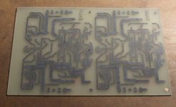
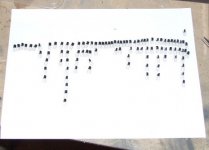
Nice etching job. How fine did you group your MPSA18's? You have some good matches there, two main peaks in the distribution.
I'm still waiting for drivers, they did send one half and everyone shows no stock. 😡
-Chris
Nice etching job. How fine did you group your MPSA18's? You have some good matches there, two main peaks in the distribution.
I'm still waiting for drivers, they did send one half and everyone shows no stock. 😡
-Chris
That was just hFE testing with my DMM. Now I have some reasonable first matches to work with I might make a jig up and test under real conditions. The pcbs worked well with the toner transfer method, nice wide traces helps, though as you can see I still have to strip off the toner and drill, but that's for tomorrow.
- Home
- Amplifiers
- Solid State
- Explendid amplifier designed by Michael Bittner, our MikeB