Hi Guys,
Thanks for taking the time to look this over. I'd like to verify some of the readings but while poking around with the probe I fried R26. I relaced it and all of the drivers and outputs but I am getting rail voltage on the output now. I've got worse problems now. 🙁
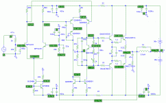
Has anyone done a chart such as the one that I posted with correct voltages? That would probably get me closer to solving what I've done wrong on all 4 of these boards.
I know some of what I did wrong on the first pair. For some reason, I used MPSA18s for Q5 and Q8. I discovered it when I began building the two newer board and still had a full set of BC546C devices.
I replaced them but I guess they ruined something else because they still don't work.
I'll keep at it. A chart with correct voltages would be an emense help.
Blessingsl Terry
Thanks for taking the time to look this over. I'd like to verify some of the readings but while poking around with the probe I fried R26. I relaced it and all of the drivers and outputs but I am getting rail voltage on the output now. I've got worse problems now. 🙁
Has anyone done a chart such as the one that I posted with correct voltages? That would probably get me closer to solving what I've done wrong on all 4 of these boards.
I know some of what I did wrong on the first pair. For some reason, I used MPSA18s for Q5 and Q8. I discovered it when I began building the two newer board and still had a full set of BC546C devices.
I replaced them but I guess they ruined something else because they still don't work.
I'll keep at it. A chart with correct voltages would be an emense help.
Blessingsl Terry
MPSA18 and BC546 have mirror-like pinout. Under some circumstances transitors do work when reverse biased, but I am afraid and sure that the symasym is not the case.
jmateus said:Hello Terry
Sometime ago Carlos posted a schematic of Symasym with
voltages. I'm not sure if all the readings are correct but I'll
assume so.
I'm uploading that schematic for you hoping that will help you.
Good luck
Thanks John,
That is exactly what I was looking for. Hopefully this will get me past the rough spot.
Blessings, Terry
Hi Terry,
It is sometimes helpful to connect the negative lead to the speaker output to measure bias voltages around the drivers and outputs. Referencing to ground isn't very helpful in those areas.
-Chris
It is sometimes helpful to connect the negative lead to the speaker output to measure bias voltages around the drivers and outputs. Referencing to ground isn't very helpful in those areas.
-Chris
Hi Terry !
Bad to hear that the measuring killed something... 🙁 I guess you fried Q4 or Q12, but only a guess.
The voltage chart John has posted is valid, but normaly not too useful as it is supply voltage dependent.
That's why i have a current chart on my page, with I = V/R you can easily measure the currents through resistors. For example, R10 (68ohms), if you measure 0.4 volts across it, this gives (0.4/68)*1000 = 5.88ma. This is slightly above the chart, but 20% difference are quite ok. (Real world vs sims) In fact, these are the only measurings i make in a live circuit, except when checking DC-offset. (And Vbe measurings of yourse)
The most important biasings are: R11,R5/6,R10,R15/17,R8/9.
With having reversed transistors for Q7/Q8 it's likely that any small signal transistor has blown, as everything starts at this point. The ccs formed by these set the biasing for the whole amp.
I'm sorry that you have that much trouble with symasym... BTW, have you etched symasym5_2 or 5_3 ?
Again, i can guarantee that the circuit and the board itself are working.
Can you show some photos ?
Mike
MikeB said:Hi Terry !
Bad to hear that the measuring killed something... 🙁 I guess you fried Q4 or Q12, but only a guess.
The voltage chart John has posted is valid, but normaly not too useful as it is supply voltage dependent.
That's why i have a current chart on my page, with I = V/R you can easily measure the currents through resistors. For example, R10 (68ohms), if you measure 0.4 volts across it, this gives (0.4/68)*1000 = 5.88ma. This is slightly above the chart, but 20% difference are quite ok. (Real world vs sims) In fact, these are the only measurings i make in a live circuit, except when checking DC-offset. (And Vbe measurings of yourse)
The most important biasings are: R11,R5/6,R10,R15/17,R8/9.
With having reversed transistors for Q7/Q8 it's likely that any small signal transistor has blown, as everything starts at this point. The ccs formed by these set the biasing for the whole amp.
I'm sorry that you have that much trouble with symasym... BTW, have you etched symasym5_2 or 5_3 ?
Again, i can guarantee that the circuit and the board itself are working.
Can you show some photos ?
Mike
Hi Mike,
I will try and figure out how to use the current chart. I didn't understand it but I will try again using the info you just gave. I still haven't quiet got a handle on the math for electronics yet. I know I need to learn it. Funny, back when I was in school, math was my best subject. Amazing what thirty years of idleness can do to a brain. 🙂
I have etched a pair of each series. Actually, I have 4 boards for the symasym5_2 and 2 boards for the symasym5_3. I only have two of each populated though. I was hoping to salvage the first two since they have about $80 worth of parts on them. I hate trying to swap parts to another board. I may populate the other pair and try them with some TO-3 devices just to hear the difference. That is, of course, if I can get them up and running. I really didn't think I would have a problem with the latest boards since I didn't try to tin them. I'm still not sure why they won’t work right. I'm going to go through them more carefully and look for wrong components. Sometimes I get in a hurry since my time is so limited. Rod Elliot suggests building one board at a time so you don't duplicate a mistake. I think I need to heed his advice.
I'll take some pics when I get home and post them tonight.
Blessings, Terry
Hello to everyone,
😉
OK, I like to try symasym but before I buy more trs (again!!!!) I want to ask something, I have some MJW21193/MJW21194 from ON Semi, I have never try them in any amp. Their characteristics
(at least from datasheats) are almost identically with MJL21193/MJL21194. I saw that some of you have try the MJLs in this amp, so can I use the MJWs? If not, any suggestion for the best choise is welcome.
Happy New Year
Spiros
😉
OK, I like to try symasym but before I buy more trs (again!!!!)
I want to ask something, I have some MJW21193/MJW21194 from ON Semi, I have never try them in any amp. Their characteristics (at least from datasheats) are almost identically with MJL21193/MJL21194. I saw that some of you have try the MJLs in this amp, so can I use the MJWs? If not, any suggestion for the best choise is welcome.
Happy New Year
Spiros
Hi Spiros, the MJW and MJL are identical except the case, the MJW has bit less power but should not be a problem. Yours should work fine !
Welcome,
Mike
Welcome,
Mike
Thanks Mike, I'll try them asap, by the way congratulations , your design is one of the most popular in the forum Spiros
Sorry Mike, one more question, is the layout in your webpage the final or you will publish a newer one? (Ok, I'm reading the whole thread carefully right now....)
Spiros
Spiros
Hello
Mike published symasym v5.3 in this thread, but i thke all file und put them on my website.
Have a look: symasym v5.3 PCB .
Or see MikeB orginal Post #1292 .
Mike published symasym v5.3 in this thread, but i thke all file und put them on my website.
Have a look: symasym v5.3 PCB .
Or see MikeB orginal Post #1292 .
I've uploaded latest files for PCB:
Quasi Silk screen 80kb
File for print out (600dpi,zipped bitmap) 45kb
Eagle files 37kb
Don't forget, it's not fully tested, i just made one board and it worked fine...
The REs in input-LTP are reserved and can be skipped by 2 small wires. (just wanted to have the possibility,principally with 22ohms they enable to increase the 499ohm in feedback to 1k to lower gain, not tested yet)
Hei Mike and guys
I hate to be posting things just for posting, but today I have to
let you know about my latest experience with my Symasym.
I was listening to a CD that I have for quite a while but for some
reason I don't listen to it very often, DIANA KRALL, Love Scenes
the amplifier makes her voice even more voluptuous, more
sensual in a way that I do not remember to have listen her.
The CD has an excellent recording as others of her, but for
some reason through this amplifier everything is multiplied by
ten, even her body........
Cut number 11 knocked me off.
Kidding apart, this is a CD to recommend.

jmateus said:
I was listening to a CD that I have for quite a while but for some
reason I don't listen to it very often, DIANA KRALL, Love Scenes
The CD has an excellent recording as others of her, but for
some reason through this amplifier everything is multiplied by
ten, even her body........
Cut number 11 knocked me off.
Kidding apart, this is a CD to recommend.
I can compare with the same on SACD, and I recommend the SACD even more, you will get an impression of one order higher ... 😉
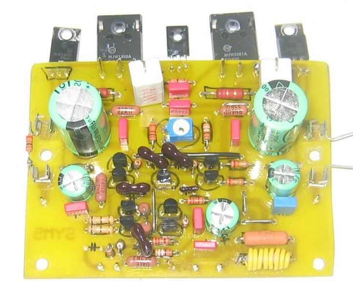
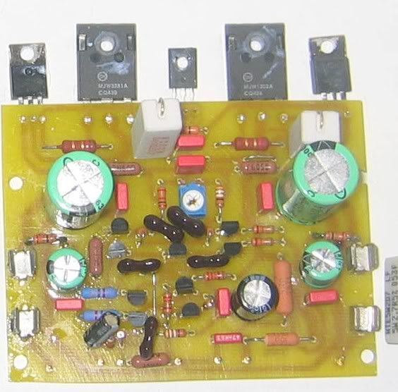
Oh boy Terry, you exchanged 3281 and 1302 power transistors, as I can see from http://www.diyaudio.com/forums/showthread.php?postid=800444#post800444
This will never work, correct it.
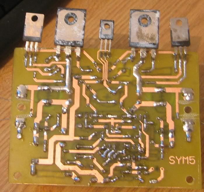
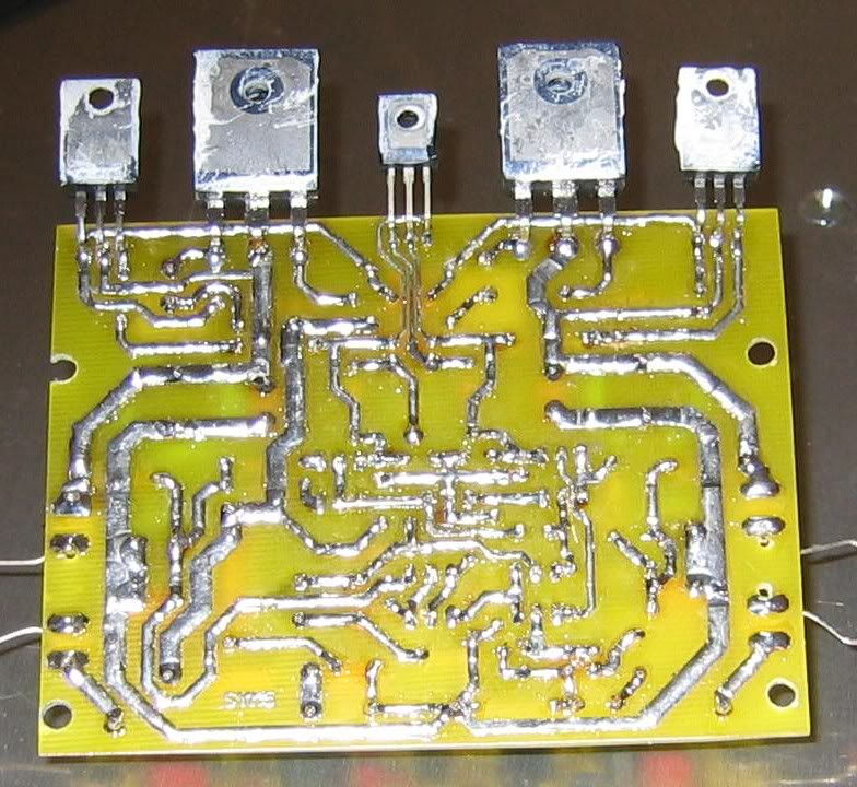
The wrong parts are on upper photo (1st). The 3rd photo (from up) has power transistors in correct positions.
This will never work, correct it.
The wrong parts are on upper photo (1st). The 3rd photo (from up) has power transistors in correct positions.
Hej Pavel,
do you think that 2SC2922/2SA1216 will work as output devices? I have got 2 spare pairs...
do you think that 2SC2922/2SA1216 will work as output devices? I have got 2 spare pairs...
Hi Terry !
Pavel is right, you exchanged the 3281 & 1302, this might explain the sudden full rail voltage at output.
Also check the soldering i have marked, on photo it looks like a solder bridge. You might consider cleaning the solder side, it is easier to see bridges, removes small balls of tin, and some flux can get wet with time and start conducting. Is this the board you have measured ?
The emitter resistors in input-LTP were intended to be shorted with wires, did you use 22ohms ? If yes, you can keep them, they do no harm, they reduce open loop gain, giving more safety margin for feedback, but reduce feedback by 6db.
BTW, your etching looks well done, which transfer method are you using ?
Padiamecki, the 2SC2922/2SA1216 are fine, Carlos uses them and they are well regarded. You might get some trouble with the board layout as the MT200 case fom the Sankens is a bit big. But maybe they still fit.
John, thanks for the compliments, looks like Diana Krall and symasym are made for each other... 😀
I had a similar experience with a Chris de Burgh (The getaway), this disc is suddenly so much fun to listen to...
Spirtos, like Uwe posted, the symasym5_3 is the latest, i will soon update my page. The circuit is the same, just an improved board layout.
Uwe, how is your symasym ?
Mike
Attachments
- Home
- Amplifiers
- Solid State
- Explendid amplifier designed by Michael Bittner, our MikeB