Hello Mike,
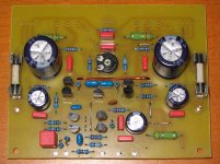
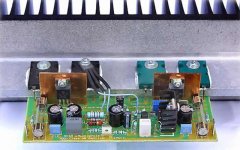
i have 4 PCB + solderd AMPs here, i have no desire today to finish it.
I must drill the head sinks and solder the five BJTs on it.
I start with a wood housing box, but i can't find a 19" case on eBay for my 4 amps.
So i will search for some time now....
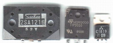
If you plan a high power version, i can give you the 1st pair BJTs two match 2SC2784 as a relasement for the MPSA18.
By the way, i finished 3 PCB for
i) ESP Project 33
ii) Power PSU 13,8V 30A, linear, with TL431 and LM317T as line regulator and 4x 2N3771 as power driver BJT.
Current Fold Back and "kurzschluss fest" not proven yet...
iii) Project 39
i have 4 PCB + solderd AMPs here, i have no desire today to finish it.
I must drill the head sinks and solder the five BJTs on it.
I start with a wood housing box, but i can't find a 19" case on eBay for my 4 amps.
So i will search for some time now....
If you plan a high power version, i can give you the 1st pair BJTs two match 2SC2784 as a relasement for the MPSA18.
By the way, i finished 3 PCB for
i) ESP Project 33
ii) Power PSU 13,8V 30A, linear, with TL431 and LM317T as line regulator and 4x 2N3771 as power driver BJT.
Current Fold Back and "kurzschluss fest" not proven yet...
iii) Project 39
MikeB said:Spirtos, like Uwe posted, the symasym5_3 is the latest, i will soon update my page. The circuit is the same, just an improved board layout.
Uwe, how is your symasym ?
MikeB said:Hi Terry !
Pavel is right, you exchanged the 3281 & 1302, this might explain the sudden full rail voltage at output.
Also check the soldering i have marked, on photo it looks like a solder bridge. You might consider cleaning the solder side, it is easier to see bridges, removes small balls of tin, and some flux can get wet with time and start conducting. Is this the board you have measured ?
The emitter resistors in input-LTP were intended to be shorted with wires, did you use 22ohms ? If yes, you can keep them, they do no harm, they reduce open loop gain, giving more safety margin for feedback, but reduce feedback by 6db.
BTW, your etching looks well done, which transfer method are you using ?
Mike
Oh my! What a dope. That's what I get for hurrying.

They are only that way on one board. I will change them.
The soldering is OK where you show. I am having a hard time getting my camera to give a clear shot of the foil side. Too much glare or something.
I did scrub the foil side with alcohol just before taking the pictures. I'll try something a little stronger.
I don't know what the emitter resistors in input-LTP are. Can you tell me the part numbers? I tried to follow the BOM. I don't have a clue how the parts work together so I don't try changing a design if I can help it.
I use the blue Press n Peel sheets for transfer. They don't work as well as I would like but once you get it to stick it works fine.
I was able to get one board to read properly last night but I didn't try to play any music through it. Seems it was showing rail voltage at the output at first and then started reading OK after a couple of minutes. Any idea what could have caused that?
I plan to use it as a model to check the other boards. After I change the outputs on the one that is.

Oh, I used two 100ohm resistor in parallel for R31 and R32. I didn't have any 47ohm resistors. Is this OK?
Thanks, Terry
Hi Terry !
Yes, hurrying = needs more time...
Keep the alcohol for cleaning, with anything stronger you will destroy something, just a toothbrush and alcohol...
I meant r16/r19, they are not on schematic, on board they are close to the mpsa18.
The 2 100ohms paralell are fine. As long as DC-offset at output is above 10mv, the amp is not functional, do not try to connect a speaker. See attachement for a symasym5_3, it is missing the outputstage and r7, but shows well the rest...
BTW, showing rail voltage at output is like complete failure...
Mike
Attachments
MikeB said:
Keep the alcohol for cleaning, with anything stronger you will destroy something, ...
Oh really? ..... don't tell me ... 😀
Oops, what are you using ? Aceton ? Laque thinner ? Or even worse ? 😀
I thought of every substance that is able to melt plastique might be bad for electronic parts...
Mike
I thought of every substance that is able to melt plastique might be bad for electronic parts...
Mike
MikeB said:Keep the alcohol for cleaning
I think maybe Pavel has other possible uses for the alcohol
😉
Sheldon

MikeB said:Hi Terry !
Yes, hurrying = needs more time...
Keep the alcohol for cleaning, with anything stronger you will destroy something, just a toothbrush and alcohol...
I meant r16/r19, they are not on schematic, on board they are close to the mpsa18.
The 2 100ohms paralell are fine. As long as DC-offset at output is above 10mv, the amp is not functional, do not try to connect a speaker. See attachement for a symasym5_3, it is missing the outputstage and r7, but shows well the rest...
BTW, showing rail voltage at output is like complete failure...
Mike
Hi Mike,
In your pic it looks like you have jumpers where R13 and R14 are supposed to go. Is that a ceramic in C14? Is this OK? Whe do you find that nice PP for C1? do you have a part number? All I have been able to find is bipolar electros for there.
I was reading 10mV at the output. I don't know why I saw rail voltage at the output at first. It went away after a minute or so. Never did it again. Also, Where do you find that nice enamaled wire? I can't seem to find a source.
Thanks, Terry
Hi Terry,
R13/14 are where are they supposed to be. The wires are for r16/r19, these are not on schematic. Yes, c14 is ceramic i had no 10pF mica at hand and have not ordered new parts yet. It seems not to really harm, but shouldn't be there. Except transistors i source all parts at www.reichelt.de , they have all the stuff you need for any electronics (won't help you, it's a german store). C1 is a WIMA-MKS2, 4.7uF. AFAIK, WIMAs are not easy to get in US... Enamelled copper wire should not be difficult to get ?
With the 10mv at output, are you able to adjust the bias in outputstage ? To be sure with this channel, measure the currents at the resistors mentioned. R8/9 should be somewhere between 3-7mv. If R15 AND R17 measure ~0.4v, the amp should be functional. 🙂
Maybe c19 was fully charged from a previous failure and took some time to discharge down to 30mv again, this sounds reasonable.
I updated my page to symasym5_3 !
good luck,
Mike
EDIT: For the wima cap look here: http://www.wima.com/kurz5m.htm
Its a MKS2 Polyester film cap (PET)
R13/14 are where are they supposed to be. The wires are for r16/r19, these are not on schematic. Yes, c14 is ceramic
i had no 10pF mica at hand and have not ordered new parts yet. It seems not to really harm, but shouldn't be there. Except transistors i source all parts at www.reichelt.de , they have all the stuff you need for any electronics (won't help you, it's a german store). C1 is a WIMA-MKS2, 4.7uF. AFAIK, WIMAs are not easy to get in US... Enamelled copper wire should not be difficult to get ?With the 10mv at output, are you able to adjust the bias in outputstage ? To be sure with this channel, measure the currents at the resistors mentioned. R8/9 should be somewhere between 3-7mv. If R15 AND R17 measure ~0.4v, the amp should be functional. 🙂
Maybe c19 was fully charged from a previous failure and took some time to discharge down to 30mv again, this sounds reasonable.
I updated my page to symasym5_3 !
good luck,
Mike
EDIT: For the wima cap look here: http://www.wima.com/kurz5m.htm
Its a MKS2 Polyester film cap (PET)
MikeB said:Hi Terry,
R13/14 are where are they supposed to be. The wires are for r16/r19, these are not on schematic. Yes, c14 is ceramic
With the 10mv at output, are you able to adjust the bias in outputstage ? To be sure with this channel, measure the currents at the resistors mentioned. R8/9 should be somewhere between 3-7mv. If R15 AND R17 measure ~0.4v, the amp should be functional. 🙂
Maybe c19 was fully charged from a previous failure and took some time to discharge down to 30mv again, this sounds reasonable.
I updated my page to symasym5_3 !
good luck,
Mike
EDIT: For the wima cap look here: http://www.wima.com/kurz5m.htm
Its a MKS2 Polyester film cap (PET)
Hi Mike,
OK, I was looking at the wrong resistors. R16 & R19 are shown as 22R on the silk screen. I guess that's where I got it.
Yes, on the one board that is working, I can adjust the bias. None of the other boards at this time show any change when turning the bias pot. I have one board that seems to measure OK on the front end but I don't get enough voltage to turn on the outputs. I'll keep looking. I'm hopeful that the board that has the outputs reversed will work once I swap them. The two 5_3 boards are still a mystery at this time.
I forgot you are overseas. Mouser carries a lot of the Wima MKS2, but not in 4,7uf value. I'll keep looking.
Blessings, Terry
Hi Mike,
I've been using lacquer thinner and a toothbrush for years. Works great and does not damage anything. (Foil side only)
Now of course, I wouldn't fill my ultrasonic cleaner full of lacquer thinner and dump a board in. There is no doubt some things would not survive. The ultrasonic cleaner for one (plastic cover).
-Chris
Reichelt ships out of germany but they recently raised their minimum price to ship abroad from 50€ to 150€ 🙁 Too bad, they had prices from 30% to 50% less than what you can get in France or Belgium.MikeB said:Except transistors i source all parts at www.reichelt.de , they have all the stuff you need for any electronics (won't help you, it's a german store). C1 is a WIMA-MKS2, 4.7uF. AFAIK, WIMAs are not easy to get in US...
Out of curiosity, is there even cheaper than Reichelt for the transistors ? They seem to have all that's needed for the symasym.
Hi Ben,
I doubt there is a shop having cheaper transistors than reichelt... There is a reason why i said "Except transistors". You always get transistors from "various" manufactures, you have no idea what you get. This is quite ok for small signal transistors, but useless for power bjts. 🙁
If you have larger orders for transistors try www.digikey.com ...
Uwe, were your MJLs from Reichelt genuines ?
Terry, keep searching on the boards, you will get them running ! Looks like the one is already working. (with the bias adjustable)
Mike
I suppose you're using digikey yourself ? I was using it when I was in the US, good prices and fast shipping. But since I only need very few transistors (i only need one amp 😉 ), taxes and freight would be prohibitive.
This french shop has the toshiba www.gotronic.fr , I'm gonna send them an email to see if they're actual toshiba.
This french shop has the toshiba www.gotronic.fr , I'm gonna send them an email to see if they're actual toshiba.
😀 😀 😀 

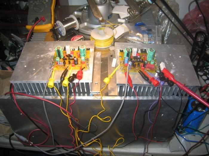
IT"S ALIVE!!!
Well I got the first two boards up and running. My Oh My, this amp sound nice! This amp has a lot of gain. I had to turn my pre down. It's louder than any of my other amps at a given pre setting. Now if I can just drive myself to get the other two boards running.
Mike, I know you've said somewhere how to go about setting the bias but I can't seem to find it. Can you run it down to me? I think I have it high but I can put my fingers right on the outputs and they are barely warm.
Thanks for all of the help. I've still got to build a case but I'm enjoying what I hear right now.
Another question came to mind. Can these be bridged? Since I have 4 boards I thought that might be a solution for those who seek higher power, though I can't imagine listening to this louder than it plays.
Blessings, Terry
EDIT:
Here's a pic of how it first came to life.
Notice the Aleph-X has become a work stand. 😀
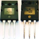
MJLs from ONS - reichelt.de
Hello Mike,
i have MJLs from ONS.
Hello Mike,
i have MJLs from ONS.
MikeB said:Uwe, were your MJLs from Reichelt genuines ?
Attachments
If someone needs more power, this Aksa can produce 220 RMS over 4 ohms
With the same wonderfull sonics compared with the Aksa 55.
Have better dinamics, better speed, a more deep bass than the 55.
And already ready...you do not need to produce boards, have silk screen, parts already selected....just put it in the holes and solder....do not need to adjust nothing, as it comes adjusted, the trimpot to adjust is there, if you need to make class A experiences.
Of course, the bigger work already done...selection, parts ordering, boards etching, boards drillling, silk screen.....this will result in bigger cost than construct with your parts....but maybe not so well matched transistors...hehe...under 3 percent!
For a while, when we are waiting Bittner design his powerfull version....as pressions are appearing in that direction, you will be very happy with Aksa....it is guaranteed too.....also GEM is nice, but cannot produce this power....well...jump into 220 watts can be interesting.
As Hugh is producing 3 new models....maybe this one's price may be interesting...there are 256 units working in USA.
Sold to Brazil, as i know, the ones i helped to construct, are only 23 for a while.
regards,
Carlos
Attachments
- Home
- Amplifiers
- Solid State
- Explendid amplifier designed by Michael Bittner, our MikeB