MikeB said:High impedance would be ~ >1kohm, good preamps have zout below 100ohms and should not show problems. /B]
No. Even 300 ohm of conventional player is too much, and no simulation will show it. The 2nd reason is to suppress HF D/A residuals by active preamp.
Okay, my experience ends here, but sims already showed that quality of signal source has greater impact than supply rail resistor... 😉 Still, the change to 47ohms is a good thing to be recommended.
Mike
Mike
I thank you by your acceptance of my arguments Mike
And the revision done into the amplifier, also Pavel support, i am turning more close Pavel..... finally!
47 ohms is much better, is a large step given to find complete stability under severe sittuations, and considering poor power supplies, that sometimes appear in our homes, beeing good business, costing low money for us too.
I Thank you very much....as you listened me with attention, even having not time enougth to read long texts.
regards Miky
Carlos
A simple buffer stage after the volume-pot should be the best to load the amp's inputstage ?
Or a buffer stage can be also sensitive to the variable source-impedance ?
Or a buffer stage can be also sensitive to the variable source-impedance ?
Yes, a buffer should do it, but need it's own power supply or beeing isolated from the amps supply with regulators.
Mike
Mike
MikeB said:Hi Terry, i've already approved the new pcb: http://www.diyaudio.com/forums/showthread.php?postid=792540#post792540
I did more listening, it does sound great. It's not tested like the old one yet, but i do not see problems.
I will update my page the next days, but likely after x-mas.
But, if you've already etched the boards... The older board is a bit easier to solder, the new one has more wire jumpers.
-----------
About the 22ohms in the supplyrails to the frontend, as Carlos pointed out, these are too small. I've spent some hours in sims, 47ohms showed the best behaviour, "matched" poles... I tried out increasing them and listened, with the 47ohms the quality slightly improved, a bit more dynamics and bass punch. I recommend 47ohms here... Thanks Carlos !
Possibly the drop in PSRR for low frequencies can be further moved to lower freqs by increasing this resistor even more, but not eliminated. I attached psrr graph, green = original 22ohms, red = 47ohms,blue = 100ohms.
It can be eliminated by cascoding the input devices, but this will be a new revision again. Maybe i will try...
I am completely happy with the quality now, so i am not sure if i will really try further modifications.
I observed that having a high impedance signal source also has a negative impact on low freq psrr. Using high gain high quality devices like the mpsa18 does help with this "issue".
Mike
Hi Mike,
This is probably a dumb question but which 22ohm resistors should be changed to 47ohm? Is it R31 & R32? R8 & R9? All of them?
Anlother thing. A few of the caps are not labeled on the silk screen. Would it be possible for you label those? I know I should be able to figure them out but I've already goofed up one pair of boards. I don't want to do it again.
Thanks, Terry

MikeB said:Hi Terry, only r31/32 should be replaced by 47ohms.
I will post picture with the labeled caps later...
EDIT: I attached pic with these 5 caps.
Mike
Excellent Mike!
Thanks so much.
Blessings, Terry
Hei Mike
What's the beef with the five caps? Any modifications on those too? Did I miss anything?
Funny, I had changed a long time ago (not a long time....) the
resistors R31/32 to 68 ohms and I realized a few points of
improvement on the sound. But now I changed back to 47 ohms
and I don't notice any difference, perhaps bcause I was used to
the sound of Symasym with those 68 ohms.
But I'll keep 47 ohms instead, just for giggs.....
This is the disadvantge of not havind the proper instruments
to check or to do bode plots....
OK, I got it, the caps are not labeled, that's what's the fuss is
all about. For a minute I thought that I had missed a thread
about the caps....
No, no reason for alarm thanks God, I don't want to do any more
modifications on the amp, it's as good as you can get it.
Now, how about the more powerful version? he,eh.... just
kidding, what's the matter, can't we make some humor on
this matter?
Mike, you are in trouble, a lot of people are asking for the 100,
200 watts Symasym, how are you going to respond? If I were you
I would be making plans for that, for some people 50 conservative
watts are not enough. I'm pretty content with this one, but if
I had an 150/200 W amplifier I would be delighted, more bandwith > more fidelity > more happiness and pleasure...
Be rested, I will not be the one to put pressure on you, but
do it, damn it!....
John,
if it was 200W, it would be something else than symasym. Let's speak about new amplifier. It is impossible to build 200W symasym by minor changes of original design.
Pavel
if it was 200W, it would be something else than symasym. Let's speak about new amplifier. It is impossible to build 200W symasym by minor changes of original design.
Pavel
Hi John !
How are x-mas preparations ?
Yes, it was about missing labeling of these 5 caps... (For symasym5_3, positioning is the same)
I can't easily convert the symasym5 to higher power, using more outputdevices and increasing the supplyvoltage does not do the job here. With higher voltage supply the small signal transistors would get very hot, but i would need even higher vas current for more power. This means, i would have to use to126 transistors instead or change topology... At these high gain levels symasym uses, triple darlington is tough to get stable, so not a choice.
I am considering using folded cascode, like the focasym mentioned at beginning of thread, it creates less phaseshift and is easier to stabilize, but will use ~18 to92 transistors, not as cute as symasym. We will see...
How many would be interested ? (should be able to work with up to 70v, ~250watts into 8ohm, in theory)
BTW, i will be out for a few days and return on tuesday.
Merry x-mas,
Mike
Naa, I dont need. Everything more expensive and bigger. If the 200W version sounds the same, why not, but will it? I have to finish my version first, all the metalwork.... 
Hi Mike,
A new 200W amp sounds interesting. I am happy with the 35~50W version for many uses. The main system however ....
I agree there is no way to scale the Symasym up, so the bigger amp would have a different sound I bet. I see very little reason to go beyond the 150~200W mark. This project may take much longer too. I'd say, polish what you have, although it is. I guess I mean investigate diff pairs etc ... When you have rested and are ready the larger amp may interest you.
I am anxious to build this one, I feel you've done a good job here.
-Chris
Hi Mike
Hi PMA
When I spoke about a higher power version of Symasym, of
course I wans't considering making improvements on the present
version, like a bigger number of output devices, bigger supply
voltage and so on....
I'm talking about another amplifier with the SAME quality of this
one but different from the rest. Would it be difficult to achieve?
Guess so....
Mike, don't consider my words any form of pressure, whatsoever
I mentioned this matter only because I took a schematic that
mentioned a higher power version of Symasym even though later
on you had said something of the effect that wasn't a valid schematic.
I wish I had the knowledge to design this amplifier and sometimes
I regret to have been just a technician working on the repair
and installation. The last years of my activity was Video, imagine!
I detest video, but Sony didn't have in the east cost a research
facility for just audio. And besides we had to make money and
numbers, not dreams...Oh, well...
Now that I am retired I regret my professional life not to have
followed another direction, the direction I took when I started
my career in electronics and I gave up because I had to make money for the family....
But this is only history from a long long time.....
Keep up the good work, guys, and a Merry Christmas to you!
Mike,
I was browsing a copy of Elektor's Hi-End Audio equipment, and found the 200W amp project has a basically identical VAS circuitry to the symasym amp. The output portion of the circuit is completely different but still for people wanting to build a 200W version that's a good starting point. The input differential uses cascoded fets and a resulated PS for each + and - voltages.
After all the talk about the rail resistor and the influence on sound I was wondering if you tought about putting in a series regulator.
Symasym is also very similar to Hafler Dynaco 400 and to DPA280 by Pavel Dudek (Upupa Epops).
Hi Guys,
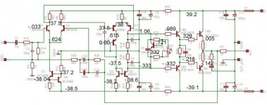
I've just finished etching two of the newer boards and filling them with parts. I still have problems. One board is not drawing too much power so I took measurements and put them on a schematic. I'm hoping one of you will be able to see were things are going amiss.
Thanks, Terry
I've just finished etching two of the newer boards and filling them with parts. I still have problems. One board is not drawing too much power so I took measurements and put them on a schematic. I'm hoping one of you will be able to see were things are going amiss.
Thanks, Terry
Attachments
Terry,
I'd say there is a problem with the bias voltages. In particular the -.333 V on the bottom base seems troublesome. I think it should be the about the same as the upper base value but negative.
I'd say there is a problem with the bias voltages. In particular the -.333 V on the bottom base seems troublesome. I think it should be the about the same as the upper base value but negative.
Hi Terry !
You're right, the readings indicate some problem...
The good news: inputstage and first part of 2nd diffamp show correct reading, 2nd diffamp is biased with ~6ma. The odd thing: the left part (r15) shows correct 3ma, but r17 shows no current at all. Where are the other 3ma going ? I suspect q9 having a short/cold solder/defect. Check q9,r18,r20,c3,c4,q3, somewhere here might be something wrong.
Also check outputstage/vbe multiplier, the problem is somewhere starting at vas output...
Can you confirm reading at r17 ?
Mike
- Home
- Amplifiers
- Solid State
- Explendid amplifier designed by Michael Bittner, our MikeB