doggy said:What you see there is running through a rectifier and cap; that is dc voltage on the meter.
cheers
doggy🙂
Then it will be suitable!
But: let's measure the ohmic resistent of the primer and secunder windinngs! Maybe the trafo will gives too much heat when pushing the Symmasym modules... If the coils resitences are too much, the losses will be too high!
Doggy
Sorry, I misread your post...
However I still think 38 Vdc is kind a too much for this amplifier,
I built three already and the last one has 32 V, the first one
had 28 Vdc.
But let's wait for Mike and see what he has to say, because
the lastest schematic had 32 Vdc and I tried to stick within the
voltage range.
This trafo has several outputs and inputs it would appear; the input side is the left side, grey brown, the ac in, the output were one black ct and 2 red. 2 composite bridge rectifiers sounds good; I have allways used made up bridge rect. before. I will try and measure the ohms; this is new territory for me. I can say the trafo is fairly heavy.There may be an alternate input to lower voltage which I have not explored yet
cheers
doggy🙂
cheers
doggy🙂
Attachments
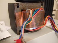
doggy said:This trafo has several outputs and inputs it would appear; the input side is the left side, grey brown, the ac in, the output were one black ct and 2 red. 2 composite bridge rectifiers sounds good; I have allways used made up bridge rect. before. I will try and measure the ohms; this is new territory for me. I can say the trafo is fairly heavy.
cheers
doggy🙂
Dont think it will work with a center tapped transformer... (two rectifiers I mean).
Take
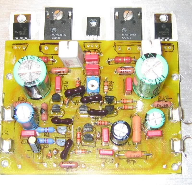
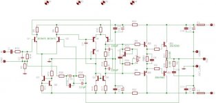
Well I've got it together but I have something wrong. The one board is smoking R32 and the other board is smoking R10. Very strange. I can't see any solder bridges and I checked all of the transistors for shorts and can't find any. Anyone got some places to look for the problem?
Thanks, Terry
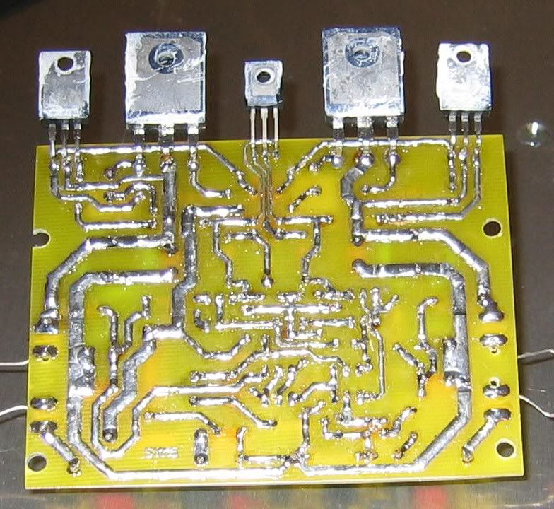
Edit: Here are a couple of pics
Thanks, Terry
Edit: Here are a couple of pics
hi terry,
Which transistor have u used mpsa18 or bc550 coz both have reversed pinouts.
Check for the shorted "emitter" pin of 1302a with its lower track(i suppose but may be wrong).I see it in ur pcb (bottom)
Remove excess solder from the pcb tracks.
At first connect all the transistors with wires and attach them to
heatsink(not on board) coz its easy remove trannys and test them.
Keep the bias pot to minimum.
Check if any transistor shorted with heatsink.
Use 12-0-12 /500ampere at first and look for the warming of any semiconductor and the sound with attached speaker.
.......I have built three of these amps and all are working perfectly well.
....very very sorry if u have done all these.....🙂
Aman
aman said:hi terry,
Which transistor have u used mpsa18 or bc550 coz both have reversed pinouts.
Check for the shorted "emitter" pin of 1302a with its lower track(i suppose but may be wrong).I see it in ur pcb (bottom)
Remove excess solder from the pcb tracks.
At first connect all the transistors with wires and attach them to
heatsink(not on board) coz its easy remove trannys and test them.
Keep the bias pot to minimum.
Check if any transistor shorted with heatsink.
Use 12-0-12 /500ampere at first and look for the warming of any semiconductor and the sound with attached speaker.
.......I have built three of these amps and all are working perfectly well.
....very very sorry if u have done all these.....🙂 Aman
1) mPSA18
2) I checked for shorts between each of the pins of each transistor but not to ground for each one. I will try that.
3) I did tin all of the tracks with solder but didn't think I had excess.
4) I did check for shorts to the heatsink before I powered anything up. There are still no shorts there.
I can set the voltage to 12VDC with my variac but I don't have a way to adjust the amperes.
I will check for shorts from ground to each pin and see what I find.
I used 100R resistors in place of the fuses at first. It smoked them once I got the voltage upt to about 20VDC. I read PMA's site and saw that he used 3ohm for that so I replaced them with 2.7ohm that I had on hand. I reads about 1.5V drop across those.
Blessings, Terry
Terry-
I used 100R resistors in place of the fuses at first,It smoked them once
-------------------------------------------
what wattage are the 100 resistors, also by the looks of what
you're saying the output is drawing large amounts of current
Try to reduce bias current by trimpot, also recheck your assembled
components in case of a mistake
cheers
Terry might have destroyed some of the transistors. Blown 100R resistors were like blown fuses. If one of the fuses blows, there appears unpredictable voltage over transistors (may be reverse polarized) and they can break. Mike knows which of the fuses blown is more critical.
built the amp
hi PMA
I have built the symasym5 modified by u using c5200/a1943 and sounding good. Is there any latest modification ????
Coz i m going to built the latest sym pcb with genuine faichild c5200/a1943 (original toshiba not available here).
plz suggest if anything new with u..........
Thanks
aman
hi PMA
I have built the symasym5 modified by u using c5200/a1943 and sounding good. Is there any latest modification ????
Coz i m going to built the latest sym pcb with genuine faichild c5200/a1943 (original toshiba not available here).
plz suggest if anything new with u..........
Thanks
aman
Attachments
Hi Terry,
I am sorry to hear that the amp did not work...
I can only think of 3 possibilities to have a pcb not working.
- you might have overlooked a solder bridge, the one mentioned by aman looks like one. Also check B-C of q5, a short here would be destructive.
- a faulty transistor
- reversed supplyvoltage ?
I suggest cleaning the board after soldering, i use a toothbrush and alcohol to get rid of all flux. Then triplecheck again for solderbridges. You need excessive currents to blow a resistor like that, it's likely that some of the small transistors are blown now. Take them out and measure. Replace the 68 ohms and the 22 ohms (r10,r31,r32).
Have you verified that none of the pins on the solder side were touching the heatsink ?
Have you used bc546b for q7/8 ?
The fault is likely to be somewhere in the frontend, there was a severe short to take out the resistor like that.
Your c14 looks very big, are you sure that this is a 10pf (or22pf) ? I recommend 10pf here, but this can't have an effect like that.
Keep the 100 ohms in the fuseholders, idle-current should not exceed ~10ma, 1v across the 100ohms. (without the oututstage biased)
If you keep the elyt as inputcap, change the polarity (inputoffset is negative), but this also does not create problems like that... And, r7, short it or wind the coil around it, otherwise you won't have much output.
Don't give up, i can guarantee that the pcb itself works...
Mike
Re: built the amp
Hi aman,
I have not done any new modifications. The information on my web page is valid and reflects the latest status that I use. The amp sounds very good and there are no problems, I am enjoying DVD-audios and SACDs now, the "great leap further" 😉
Regards,
Pavel
aman said:hi PMA
I have built the symasym5 modified by u using c5200/a1943 and sounding good. Is there any latest modification ????
Coz i m going to built the latest sym pcb with genuine faichild c5200/a1943 (original toshiba not available here).
plz suggest if anything new with u..........
Thanks
aman
Hi aman,
I have not done any new modifications. The information on my web page is valid and reflects the latest status that I use. The amp sounds very good and there are no problems, I am enjoying DVD-audios and SACDs now, the "great leap further" 😉
Regards,
Pavel
hi PMA
I have got mjl21193/94(metal case) ,could i use them in symasy5 .
Would i need ur modification or can i go with the original schematic???
regrds
aman
I have got mjl21193/94(metal case) ,could i use them in symasy5 .
Would i need ur modification or can i go with the original schematic???
regrds
aman
I think that Michael was recommending them. I think that original Mike's values should be OK.
I have not tried them yet, but jmateus did and is very happy with them. Regardless of outputdevices choosen, i recommend to at least reduce the 22pf feedback cap to 10pf.
Mike
Mike
Hi MikeB,
Have you ever realized your amp in Quasi-complementary Configuration using MJL21294..Monster metal Bipolar if not, then someone is there who is going to try it in that fashion...not I am...but someone from this forum...lets check it how it goes....
regards,
K a n w a r 🙂
Have you ever realized your amp in Quasi-complementary Configuration using MJL21294..Monster metal Bipolar if not, then someone is there who is going to try it in that fashion...not I am...but someone from this forum...lets check it how it goes....
regards,
K a n w a r 🙂
 . You missed the thread.
Workhorse said:Hi MikeB,
Have you ever realized your amp in Quasi-complementary Configuration using MJL21294..Monster metal Bipolar if not, then someone is there who is going to try it in that fashion...not I am...but someone from this forum...lets check it how it goes....
Something like that: Link ? (greetings to quasi...😉)
Did sound nice, but was missing thermal compensation (runaway started after ~10minutes,exponential style). But no chance against symasym5...
Mike
- Home
- Amplifiers
- Solid State
- Explendid amplifier designed by Michael Bittner, our MikeB