And by the way...as i was forgeting
Related dear John Mateus burning amplifiers with his ESLs...well this is an old story, that only John can confirm.
He already spent enormous money burning amplifiers, and are not convinced that the problem are those eletrostátic demmons.
In the place off "shot the damn ESLs"...he is burning transistors and fets.
Well..his pleasure...but this showns to me that Symassym continue to be the same good amplifier...and that John continue to be the same good electrostatic lover.
regards,
Carlos
Carlos,
there is one thing making me sad in your posts. I have never spoken about audible distortion, but the measured one. You can never know if your amp has it or not. And you can never know what Mike's improvement sonically brought, as you have not heard it.
there is one thing making me sad in your posts. I have never spoken about audible distortion, but the measured one. You can never know if your amp has it or not. And you can never know what Mike's improvement sonically brought, as you have not heard it.
PMA said:Carlos is just pulling our leg 😀
Which one, the middle one ? 😀

That's the problem with distortions, they are not necessarily perceived as distortions... That's where measurings become handy.
Mike
Human ear is especially sensitive to non-harmonic distortions. That's why jitter, RFI/EMI mix products, quantization distortion matter. The ear is quite tolerant to low-order even harmonic distortions, especially the 2nd.
But they also do make a difference, if above masking /the higher order the worse/, and they produce non-harmonic products for more complex music, and these products do matter. There must be a comparison done, otherwise no one knows.
But they also do make a difference, if above masking /the higher order the worse/, and they produce non-harmonic products for more complex music, and these products do matter. There must be a comparison done, otherwise no one knows.
Allright, I'm pretty much sold on this project. A few questions before ordering parts.
- Is this the last layout ? http://www.diyaudio.com/forums/showthread.php?postid=783283#post783283
- If I use +/-28VDC rails, do I need to change some values ?
- I cannot easily get the original output transistors but I can get the toshiba Pavel used. The only mod needed is to modify the feedback cap ?
- Which transistors need to be matched and how close ?
Thanks a lot 🙂
Originally posted by MikeB
I overlooked your question about the matching, no complementary matching (except outputstage maybe). Match Q1 <-> Q2 , Q4 & Q12, Q3 & Q9. Match for hfe and vbe, except q3/q9, these need only vbe matching.
Also matching r5/r6 can help.
Matching between channels might be interesting for q8, and r29/30.
HTH,
Lukas
00940 said:Allright, I'm pretty much sold on this project. A few questions before ordering parts.
- Is this the last layout ? http://www.diyaudio.com/forums/showthread.php?postid=783283#post783283
- If I use +/-28VDC rails, do I need to change some values ?
- I cannot easily get the original output transistors but I can get the toshiba Pavel used. The only mod needed is to modify the feedback cap ?
- Which transistors need to be matched and how close ?
Thanks a lot 🙂
Welcome Ben !
- The link is correct, that is the latest layout.
- For +/- 28v you don't need a change.
- The Toshibas (sc5200/sa1943) are perfectly ok, i used them in my latest version.
- Match as Lukas already posted, only these pairs need matching. I matched them to ~1%, i needed about 5 devices to get this match.
I did not match the outputdevices, i just took them out of the bag.
have fun,
Michael
Well Pavel, so...Mike improve it technically and distortion that did not existed
started to exist!...ahahahha!
This is a very strange improovement. Some sound that distort and i cannot listen...only the scope or instruments can...and if i ask scope it will not answer me..so...i will never know the distortion...well...let it be!...not bothering me, do not exist to me....but exists to scope.. so, something that have existance without existing....hehe...lovely.
Well...you are sad....and i am too.
Let's go to a bar and have a drink...i will pay this time!
And not electronics conversation, as i cannot listen, and if i listened, the sound did not exist.
Cheers,
Carlos
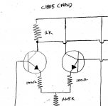
A fast off topic...someone sent me a schematic...this one i constructed and sounded
good...but i made some small modifications because treble.
I have lost your adress, i think you sent this schematic using my hotmail adress.
Well, i have the schematic, but do not have your name.
Thank you by the schematic..showing only a small part of the double differencial simetrical input.
regards,
Carlos
Attachments
new here
As stated earlier in another thread, I am looking to build another amp [well maybe 2} I started to read and reached page 24-a lot of reading to do still, so can I ask,MikeB is there a pcb made for your amp that is available to buy? I also have the aksa 55 pcbs to build. If only I was born rich-instead of good looking.
p.s. I enjoyed that picture of tha ape with the glasses! very
entertaining destroyerX
🙂 cheers
doggy
PMA said:Human ear is especially sensitive to non-harmonic distortions. That's why jitter, RFI/EMI mix products, quantization distortion matter. The ear is quite tolerant to low-order even harmonic distortions, especially the 2nd.
And 3rd.
We've all been listening to (relatively) copious amounts of H3 from
analog tape for years.
Some classical recording engineers still prefer the sound of a good
analog tape over digital.
T
MikeB:
If you alerady experienced that PCB layout is so important, why
dont you try a PCB with a whole GND layer on the top (part side) ?
This should protect, and shield the wires in some degree against
RFI and certainly should decrease EMI effects too, cause of reducing
the inductances.
Something else: did you already try snubbers in your PS ? 😀
Terry Demol said:
And 3rd.
We've all been listening to (relatively) copious amounts of H3 from
analog tape for years.
Some classical recording engineers still prefer the sound of a good
analog tape over digital.
T
Yes. But tolerance to H2 is about 10x higher in level compared to tolerance to H3.
Re: new here
Hi doggy,
There are no PCBs to sell, until now you have to make the boards yourself, that's why they are single sided.
Hey, if you're good looking, marry a rich woman... 😀
Mike
doggy said:As stated earlier in another thread, I am looking to build another amp [well maybe 2} I started to read and reached page 24-a lot of reading to do still, so can I ask,MikeB is there a pcb made for your amp that is available to buy? I also have the aksa 55 pcbs to build. If only I was born rich-instead of good looking.
Hi doggy,
There are no PCBs to sell, until now you have to make the boards yourself, that's why they are single sided.
Hey, if you're good looking, marry a rich woman... 😀
Mike
Yes, one of those ladies with the blue hair and one foot on a banana peel...making a pcb is something I have not done yet but no doubt I can learn to do.
Also MikeB where can you get those large electro. caps that you used? for the p.s. Most likely over here 10,000uf seems a practical limit; and no bypassing or snubber on p.s? I guess if it is of no effect, why use them.
cheers
doggy🙂
Also MikeB where can you get those large electro. caps that you used? for the p.s. Most likely over here 10,000uf seems a practical limit; and no bypassing or snubber on p.s? I guess if it is of no effect, why use them.
cheers
doggy🙂
Doggy
Too much voltage for the Symasym, it is supposed to be supplied
with no more than +-35 VDC.
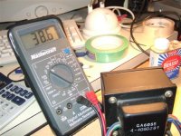
With a trafo of 38 volts, after rectified and smoothed the voltage
will be around 53 V DC which is too much...
The ideal voltage for the trafo would be around 2 x 25 volts.
Cheers
Too much voltage for the Symasym, it is supposed to be supplied
with no more than +-35 VDC.
With a trafo of 38 volts, after rectified and smoothed the voltage
will be around 53 V DC which is too much...
The ideal voltage for the trafo would be around 2 x 25 volts.
Cheers
What you see there is running through a rectifier and cap; that is dc voltage on the meter. So over voltage by 3.6 d.c-it might sag a little as well.
cheers
doggy🙂
cheers
doggy🙂
Hi doggy !
Wife with blue hair ? Etching your own boards is less ugly...
I did not think of the 22000uF beeing very big... I thought that the 47000uF might have been overkill, so bought them 2 numbers smaller. 😀 As rectifiers are not expensive, why not using 2 of them, one for each channel and use 4 of the 10000uF or 6800uF ? I bought them here in germany at www.reichelt.de ... (~8$ each)
As the amps have these 1000uf onboard, they do not put very heavy HF load to the supply and caps with not too low ESR in PS shouldn't hurt much. I tried some snubbers but heard no improvement, i only kept a 500ohms + 100nf in series in front of the rectifiers on AC side, according to sims it should completely eliminate diode ringing. Adding the wrong stuff here can turn the diode ringing into oscillation, without scoping the result it might be better to add nothing. But, i am not very experienced with PSUs... 🙁
About your transformer, 38v DC should do no harm, but is upper limit...
Is the transformer ~25v AC ? Jmateus is right, a tranformer with 2x25v AC is the perfect one.
Mike
Wife with blue hair ?
Etching your own boards is less ugly...I did not think of the 22000uF beeing very big... I thought that the 47000uF might have been overkill, so bought them 2 numbers smaller. 😀 As rectifiers are not expensive, why not using 2 of them, one for each channel and use 4 of the 10000uF or 6800uF ? I bought them here in germany at www.reichelt.de ... (~8$ each)
As the amps have these 1000uf onboard, they do not put very heavy HF load to the supply and caps with not too low ESR in PS shouldn't hurt much. I tried some snubbers but heard no improvement, i only kept a 500ohms + 100nf in series in front of the rectifiers on AC side, according to sims it should completely eliminate diode ringing. Adding the wrong stuff here can turn the diode ringing into oscillation, without scoping the result it might be better to add nothing. But, i am not very experienced with PSUs... 🙁
About your transformer, 38v DC should do no harm, but is upper limit...
Is the transformer ~25v AC ? Jmateus is right, a tranformer with 2x25v AC is the perfect one.
Mike
- Home
- Amplifiers
- Solid State
- Explendid amplifier designed by Michael Bittner, our MikeB