Hi
These should be ok, although I cannot comment on how they might sound.
Maximum pot resistance (R22) represents maximum conduction of T1 = minimum output stage quiescent current.
If using 4 ohm speakers, the output power will be around 100 watts, which is slightly more than the transformers will cope with when running at continuous power, due to amplifier efficiency. In this situation, 160 VA might be better. For 8 or 6 ohm speakers, 120 VA per channel should be adequate.
Regards,
Steve
quicknick said:First, I don't have any MJL transistors but I have a few pairs of NJW3281/1302. Can I use them instead?
These should be ok, although I cannot comment on how they might sound.
... how should R22 (the bias setting pot) be turned at first power up in order not to blow the output transistors? Minimum or maximum resistance?
Maximum pot resistance (R22) represents maximum conduction of T1 = minimum output stage quiescent current.
Can I use one 26-0-26 Vac / 120VA transformer for each channel, or would the amplifier be underpowered?
If using 4 ohm speakers, the output power will be around 100 watts, which is slightly more than the transformers will cope with when running at continuous power, due to amplifier efficiency. In this situation, 160 VA might be better. For 8 or 6 ohm speakers, 120 VA per channel should be adequate.
Regards,
Steve
This is how my boards look like (i have pre-tinned the tracks on the one at the left, the second one is covered with flux and I'll do the same to make soldering easier). As you can see they have some sort of a ground plane (not actually connected to IGND or VGND but it'll connect to chassis GND through the mounting screws). Do you think this ground plane will be OK or will it give me problems? Should I try to get rid of it? Maybe Ferric Chloride could wipe it off, but first I have to check if it doesn't corrode the solder too...
Attachments
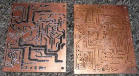
quicknick said:Do you think this ground plane will be OK or will it give me problems?
Personally, I wouldn't recommend using those boards as they stand. The "standard" PCB layout is a proven design and known to work well.
a) Track clearance with respect to the ground plane is fairly minimal and the risk of shorts would be high because of this. The supply rails are particularly vulnerable.
b) There will be an increase in the capacitance to ground at most points of the circuit (compared to a board without a ground plane). This may affect performance and stability.
Regards,
Steve
I have found that with exception of the inverting input, most Stable Audio Amp designs perform quite well with a ground plane, In fact i use one on Both sides of the board except in the area around the inverting Input. Since you already have the PC Board finished why not check for shorts and remove and plane from around the inverting input, then populate. Some sort of current Limiting would be nice upon 1st powering it up I often use a 100 watt lamp in series with the AC side for this.
I found a sample of Symassym sonics in youtube
It is interesting.... that sound quality really belongs to the Symassym...easy to recognize.
You see the metalic sounds sometimes sounds alike rice inside an aluminium can...and only sometimes...this was the earlier Symassym characteristic that was further developed...i do not what symassym was playing in this sample as many guys made other versions.
The only one i have made was the first one, the one created and designed by Michael Bittner...about the others i do not know.
http://www.youtube.com/watch?v=XFbsolcxf0E
regards,
Carlos
Hi Carlos,
This is a Brazilian Symasym, this version is 5.3, identical to the MikeB instructions.
Do you like the sound ?
best regards
hcbonfim
This is a Brazilian Symasym, this version is 5.3, identical to the MikeB instructions.
Do you like the sound ?
best regards
hcbonfim
Yes i like it very much..wonderfull amplifier
and your unit is playing fine..... now i have perceived the bamboo furniture... this is a clue about the place... Asiatic folks and also brazilians use that.
My first marriage furniture was all made using bamboo...very nice.
regards,
Carlos
and your unit is playing fine..... now i have perceived the bamboo furniture... this is a clue about the place... Asiatic folks and also brazilians use that.
My first marriage furniture was all made using bamboo...very nice.
regards,
Carlos
Nice words Carlos, thank you,
I am very impressed with symasym, spending a lot of time with delicious sound !!! Thanks to MikeB also.
The bamboo is only the support heheheh
I am very impressed with symasym, spending a lot of time with delicious sound !!! Thanks to MikeB also.
The bamboo is only the support heheheh
Thank you Carlos, i got here from Brazilian HT Forum DIY "den", and your input (and images) saved me several embarassing questions (I ended up blaming my youth experiences as a DIY'er on the "probably stale coloured little beans they sold me at S. Ifigenia").
I hope I have better luck now that I am "Old & Wise" (what??!!!??? LOL!)
Eron Silva, (now) from Israel
I hope I have better luck now that I am "Old & Wise" (what??!!!??? LOL!)
Eron Silva, (now) from Israel
Ah, the hidden stepping stones...
Carlos, that has always been my (very neurotic) greatest fear: the "cat's jump" (our very familiar brazilian tale of the "pulo do gato"). I have failed too many times, including when trying to make a signal injector to detect what had gone wrong... Oh, dang! Lasquera!
I have saved the images of the symasym schematics, pcb printout and pcb copper side view you have published in another thread... guess it will be safer to ask your guidance (if you don't mind...) regarding which is actually the right schematic, before putting the hand into my shallow, scorpion filled pocket (no jewish joke here, please!😀)
Eron Silva, From Pernambuco to Israel via Sao Paulo
And i ensure you that those parts are the ones that aid the beautifull, unbeatable treble.
There are small parts underboard, and some special components, not only related the material used to produce the parts, but also the strange and tuned values.
...
Carlos
Carlos, that has always been my (very neurotic) greatest fear: the "cat's jump" (our very familiar brazilian tale of the "pulo do gato"). I have failed too many times, including when trying to make a signal injector to detect what had gone wrong... Oh, dang! Lasquera!
I have saved the images of the symasym schematics, pcb printout and pcb copper side view you have published in another thread... guess it will be safer to ask your guidance (if you don't mind...) regarding which is actually the right schematic, before putting the hand into my shallow, scorpion filled pocket (no jewish joke here, please!😀)
Eron Silva, From Pernambuco to Israel via Sao Paulo
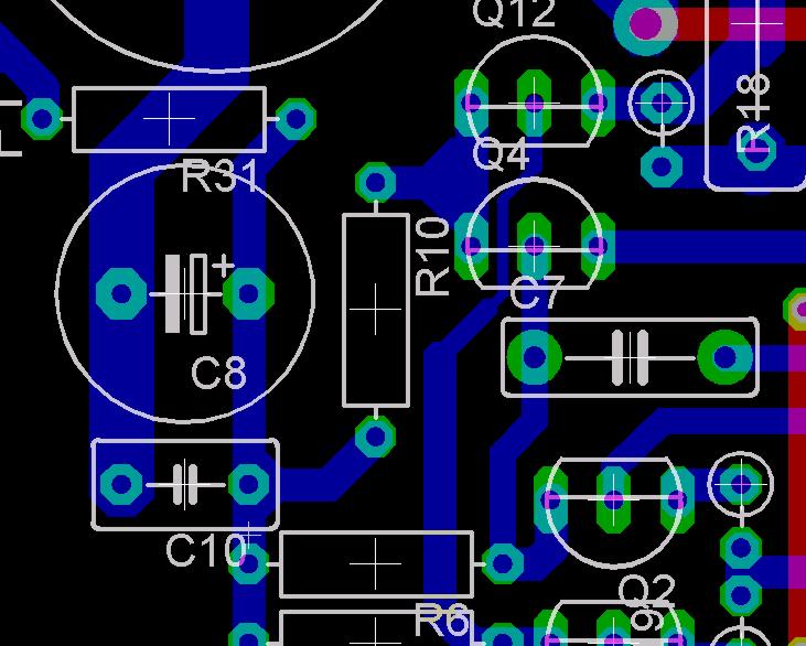
I manage to swap original layout to MT200 power transitor layout. I want to etch my self board. To make it more easy i change some route that was going between small T92 transitor. I shaown you the original layout and then my modification. Can somebody tell me if my modification will impact final result? Was there any raison forthe original layout with a so thin trace that goes between TO92 pad (more deficult to etch, possibility of shortcurt...).
Here is the original
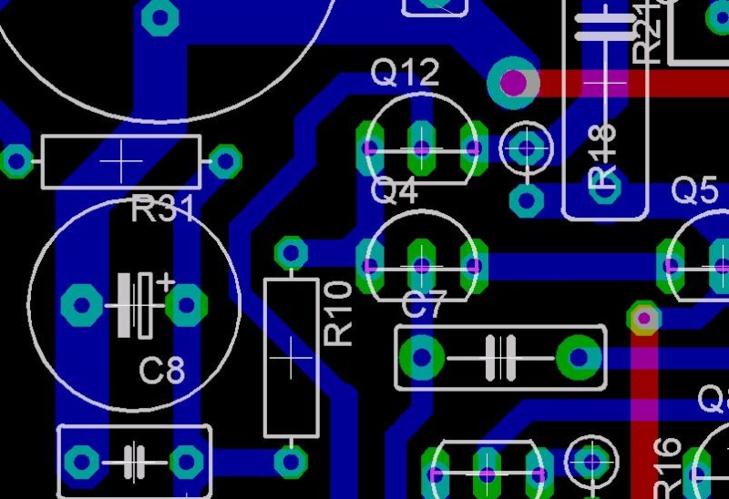
My modification
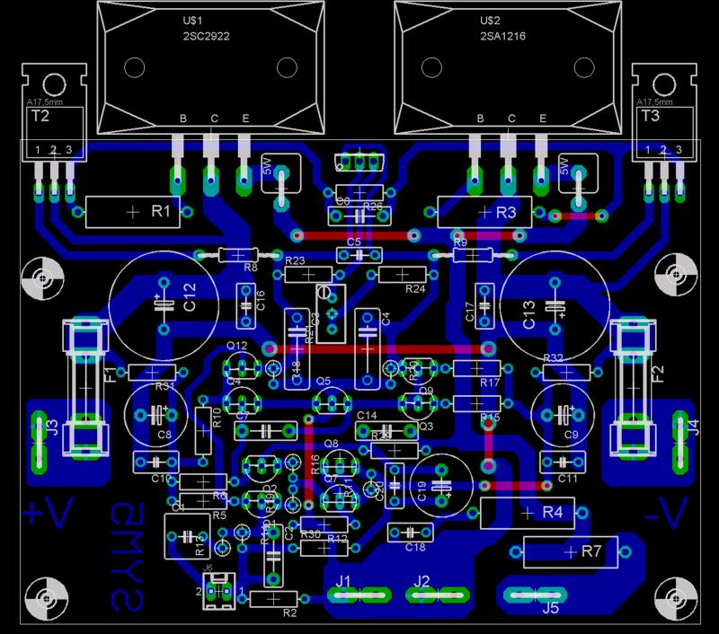
Here is the my symasym version (little changes in fact)
Marc
Here is the original
My modification
Here is the my symasym version (little changes in fact)
Marc
Hi Marc,
I like the rerouting of that trace. Interesting use of the other output transistors. These are also very good and should work well. Expect to play with the compensation capacitor a little. That goes for everyone who either changes the layout or drivers and / or output transistors.
Mine sound great, but I haven't really been able to experiment with them yet. A very worthwhile project, they exceeded my expectations. I expected good sound, they performed much better.
Hi quicknick,
As currentflow pointed out, use them, but be sure to eliminate any possible short circuits. Be ruthless and remove anything that may possibly get too close for comfort. You must remove all flux in order to examine your connections. Also, as ppl pointed out, capacitance around the inverting input is most unwelcome. This could cause the amp to oscillate and fail.
Everyone,
Enjoy this delightful little amplifier, and don't worry about the exact amount of power yours will deliver. It is powerful enough for most reasonable listening without pushing it.
-Chris
Thank you Bonfim and Eron Silva..... the Symassym is a very nice amplifier
I love it deeply, has a very nice reproduction and a wonderfull punch into the bass..also great dinamics.
Was a very good job Michael Bittner has done together a lot of good people that have cooperated.
abraços,
Carlos
I love it deeply, has a very nice reproduction and a wonderfull punch into the bass..also great dinamics.
Was a very good job Michael Bittner has done together a lot of good people that have cooperated.
abraços,
Carlos
I love it deeply, has a very nice reproduction and a wonderfull punch into the bass..also great dinamics.
Was a very good job Michael Bittner has done together a lot of good people that have cooperated.
abraços,
Carlos
Hi Carlos, I know that, and that' why i asked about my modification since i don't want tro degrade the grate job that do Michael Bittner. I want to build two channels for stereo set-up and swap them after in a 5ch configuration form suround. LCR would be brother of Quasi (a another great design).
anatech said:Hi Marc,
I like the rerouting of that trace. Interesting use of the other output transistors. These are also very good and should work well. Expect to play with the compensation capacitor a little. That goes for everyone who either changes the layout or drivers and / or output transistors.
I read in this topic (if i'm not wrong) that the original layout and caps value is ok for 2SC2922/2SA1216 2SA1837/2SC4793 without any changes.
Marc
Thanks for your input, currentflow and anatech. I completed both boards a month ago, after stripping the groundplane completely. It came off surprisingly easy, using a sharp cutter and a pair of tweezers.
Here's a picture of how the thing looks like at the moment. But the sound, oh the sound, it's so "alive" and enveloping that I already ordered a cool case from an Italian outfit 😀, and that case will be stuffed with lots of other goodies besides the amp boards and power supply. But more on that later, when it'll be finished. Here it is, you can laugh of course, but it's just a testbed:
[img=http://img143.imageshack.us/img143/84/dscf2526.th.jpg]
The transformer is a 300VA unit with quad 27V ac secondaries, electrostatic and electromagnetic screens. Filtering is 4x15,000uF/63V per channel, Nippon Chemi-Con. Wired point to point at the moment, but I'll build a board that will use Schottky rectifiers. I used as output devices the NJW0302/0281 pair - lowest power of all ONSemi offerings, but I can replace them at any time with NJW1302/3281 or even MJL's if you guys think that the ones used by me are too flimsy.
Last edited:
can i replace the output transistors with mjl21193-mjl21194 and the driver transistors with 2sa1837 and 2sc4793???
- Home
- Amplifiers
- Solid State
- Explendid amplifier designed by Michael Bittner, our MikeB