HI
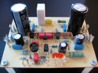
I'm in the proces to finnish these amplifier , maybe at the next week will be done .I just got the new power transistors from ON Semi , I waited on them from May .
I would like to have a question ,do I have to use a preamplifier to drive the amp or it is enough to use a simple poti .
Please let me know .
Regards
gaborbela,
Symasym's gain is high enough so that a preamp is not needed.. This was a design goal of MikeB...
Cheers
Symasym's gain is high enough so that a preamp is not needed.. This was a design goal of MikeB...
Cheers
HI Michael!
yes, you killed my belief, that high nfb amps sound harsh
but everyone here agrees that it is true.
I confirm Boris's note that FJLs souunds very good.
😕 The only thing I am confused is what bias to set?
Your first proposition was 55mA, some people proposed more, Pavel used 400mA, last proposals were 22mA because of crosover dist and supply niose...
Could you give your proposal regarding the bias?
Thank you in advance!
Hi Borys, can you describe how the high tones improved from the MJLs to the FJLs ? Yes, low outputcapacictance does speed up the amp, but i have the feeling that linearity of these transistors is more important.
Gaborbela, as clem said, symasym's gain is high enough to be driven without preamp, but a unityain buffer between pot and amp should help.
Padamiecki, it's difficult to say which bias is the right one, i suspect that each device has it's own optimal bias. The only way out would be listening to these 3 bias settings. Think of the 55ma as a default bias.
Loke, nice work ! No inputcap ?
Mike
MikeB said:Hi Borys, can you describe how the high tones improved from the MJLs to the FJLs ? Yes, low outputcapacictance does speed up the amp, but i have the feeling that linearity of these transistors is more important.
Mike
I think that high tones has more details and it souds more sharply. First impression is that there is more high tones in FJL version against 2pair MJL. When I'm listening to amp with farhilds I can hear more precisely stringed instruments and cymbals. There is more "air" in sound. The difference is very small but it is audiable.
Hi Mike,
I am toying with an idea. Have you tried increasing the 0.1 uF bypass caps to something like a 1 uF bypass? This may make a large difference across the feedback cap (C20).
Just an idle thought.
Hi Padamiecki,
My bias setting was done by watching the THD level on a meter at various power levels and load impedances. I also monitored the residual output from the meter on an oscilloscope. This allowed me to see the actual crossover distortion while the fundamental was suppressed by 60 ~ 80 dB. I'm sure this will vary with different output transistors and possibly driver transistors.
If you read both Pavel's and Mike's writings, you will see they have already found differences between output pairs. The compensation capacitor will also vary with output transistor choice. Look at the 1 KHz and 10 KHz squarewave waveforms to adjust this value. Make sure to include some capacitance and inductance if you want to "push" the limit with this value. That way you can ensure it is stable with different loads.
-Chris
Hi Al,
Once you hear it, it will be all worthwhile. 😎
Stay tuned for improvements as they are found.
-Chris
Once you hear it, it will be all worthwhile. 😎
Stay tuned for improvements as they are found.
-Chris
Chris, could you do a quick test with your variac for me, and see how the amp runs on 16V rails? I have a cunning plan... 😉
Hi Al,
It would be easier for me to hook it up to a DC power supply, would that be okay?
 😀
😀
That will have to wait for this weekend though.
-Chris
It would be easier for me to hook it up to a DC power supply, would that be okay?
😀 That will have to wait for this weekend though.
-Chris
Bias
Depends what you are looking for, guys. 22mA etc. will give you quite typical transistor sound. I set 400mA in order to get most pure, clean sound from this amp, for all levels. I do not get higher not to create a heating.
Depends what you are looking for, guys. 22mA etc. will give you quite typical transistor sound. I set 400mA in order to get most pure, clean sound from this amp, for all levels. I do not get higher not to create a heating.
Pavel, i guess that the high bias is not to reduce crossover distortion, but more to keep transistors at high ft and less dynamic behaviour ?
I guess that i do not hear difference between 22ma and 110ma as the rest of my equipment might be limiting. Signal source was unmodified pioneer 575a 🙄
Al, have you put the 2k to the input below the pcb ? No time for transistors ? 😀
Chris, i have not played with the 100nf bypass cap to c19, on my prototpe i used an old/cheap elyt, and symasym sounded "lovely" colorized After adding the 100nf all colorizing was gone and i kept it since then...
Mike
I guess that i do not hear difference between 22ma and 110ma as the rest of my equipment might be limiting. Signal source was unmodified pioneer 575a 🙄
Al, have you put the 2k to the input below the pcb ? No time for transistors ? 😀
Chris, i have not played with the 100nf bypass cap to c19, on my prototpe i used an old/cheap elyt, and symasym sounded "lovely" colorized
After adding the 100nf all colorizing was gone and i kept it since then...Mike
Hi Mike,
Okay, when I get to this I will let you know. I have some 1 uF on hand to try it.
Hi Pavel,
The change in bias currents from very high to 20 mA sounded about the same. With the MJW outputs things may be different. I also matched everything including the outputs.
-Chris
Okay, when I get to this I will let you know. I have some 1 uF on hand to try it.
Hi Pavel,
The change in bias currents from very high to 20 mA sounded about the same. With the MJW outputs things may be different. I also matched everything including the outputs.
-Chris
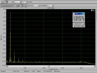
The difference can be both heard and measured. I recommend a good preamp, it may be a buffer preamp with +1 gain. The OPA2134 is nothing that special, better take 2 x OPA627 (much better). As a signal source I use modified SONY CDP-XA2ES. The analog circuits are modified - ICs changed, output electrolyte cap thrown away, mute transistors cutted, flat ribbon 30cm cable from analog stage to headphone board taken away, output impedance reduced to 200 ohm. It changed players sound, and measured HF stuff at the ouput reduced considerably. See the spectrum:
Attachments
The opa132 is a bit more stable in unity gain than the opa134 in my experience and sounds the same. Biasing it in some kind of class a helps a bit.
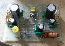
All those discussion pushed me to recase my symasym into a proper enclosure. Well, almost since I used an old VHS case with a wooden front. It includes a "preamp" section (opa132 buffer-balance-volume-opa132 buffer again)and a phono preamp (scavenged from a vintage H-K amp, with all caps changed).
In a system made of a Thorens TD166 with AT95E, a Philips CD930 slightly modified and a pair of DIY speakers (Vifa P17WJ and D25TG in a TL), the symasym is clearly not yet the limiting link. A lowish bias doesn't affect the sound in that system, so I let it low to keep the amplifier cool.
I'll try to drop a picture of the amp tomorrow.
Many thanks again to Mike for sharing his time and work 🙂
Re: Bias
Unfortunately it is my experience that if you try 1A then you
may not want to go back to 400mA... so probably don't try it 🙂.
We have an OP stage design that is close to Halcro linear with only
local error correction / feedback, extremely fast, yet it still responds
sonically to more bias... tried up to, from memory, 1.5A settled on
1A.
It really is frustrating sometimes, that's a lot of heat to get rid of,
needs special measures (fan+tunnel) and costs a lot... oh well.
WRT FFT, what soundcard, software are you using? The residual
looks -very- clean.
Is this just the pre amp, or pre + amp?
Cheers
Terry
PMA said:Depends what you are looking for, guys. 22mA etc. will give you quite typical transistor sound. I set 400mA in order to get most pure, clean sound from this amp, for all levels. I do not get higher not to create a heating.
Unfortunately it is my experience that if you try 1A then you
may not want to go back to 400mA... so probably don't try it 🙂.
We have an OP stage design that is close to Halcro linear with only
local error correction / feedback, extremely fast, yet it still responds
sonically to more bias... tried up to, from memory, 1.5A settled on
1A.
It really is frustrating sometimes, that's a lot of heat to get rid of,
needs special measures (fan+tunnel) and costs a lot... oh well.
PMA said:The difference can be both heard and measured. I recommend a good preamp, it may be a buffer preamp with +1 gain. The OPA2134 is nothing that special, better take 2 x OPA627 (much better). As a signal source I use modified SONY CDP-XA2ES. The analog circuits are modified - ICs changed, output electrolyte cap thrown away, mute transistors cutted, flat ribbon 30cm cable from analog stage to headphone board taken away, output impedance reduced to 200 ohm. It changed players sound, and measured HF stuff at the ouput reduced considerably. See the spectrum:
WRT FFT, what soundcard, software are you using? The residual
looks -very- clean.
Is this just the pre amp, or pre + amp?
Cheers
Terry
Hi Terry,
it is the CD player output. Quite ordinary sound card, but a long story 😉 .
I am attaching another image - amplitude response of a preamp in 10kHz - 400MHz range (no mistyping). Measured by Marconi Instruments 2031 signal generator.
It may look strange, but helps to understand preamp action as HF filter (if properly done) for power amplifier.
Cheers,
Pavel
Attachments
- Home
- Amplifiers
- Solid State
- Explendid amplifier designed by Michael Bittner, our MikeB