A little freedom feels good...
Attached find my layout for the symasm... I tried to shorten and optimise the feedback path, as well as adding star grounding, I also designed around 2SC5200/SA1943 as that is what I have lots of.
Any comments suggestions are welcome... this is still an early draft and has not been tested but I am reasonably satisfied that it should work... please take note of the post above about the 10pf cap... I missed it before...
Also it will use offboard fuses, I prefer case mounted fuses for ease of access.
Hit the ratsnest icon (looks like a big X) to fill in empty polygons...
Attachments
Nordic said:A little freedom feels good...
Attached find my layout for the symasm... I tried to shorten and optimise the feedback path, as well as adding star grounding, I also designed around 2SC5200/SA1943 as that is what I have lots of.
Any comments suggestions are welcome... this is still an early draft and has not been tested but I am reasonably satisfied that it should work... please take note of the post above about the 10pf cap... I missed it before...
Also it will use offboard fuses, I prefer case mounted fuses for ease of access.
Hit the ratsnest icon (looks like a big X) to fill in empty polygons...
what s/ viewer I need to view this file after I unzip?
Hi Mike,
the steps of my potentiometer are too rough to listen to the quiet music in the night,
so I connected the output through a audio transformer (taken from dead SE triode amp),
and guess what?

sound is better,
and now I can listen at the potentiometer set as MAX, this means full power? No, I do not think so,
I cannot hear the distortion...😕
the steps of my potentiometer are too rough to listen to the quiet music in the night,
so I connected the output through a audio transformer (taken from dead SE triode amp),
and guess what?
sound is better,
and now I can listen at the potentiometer set as MAX, this means full power? No, I do not think so,
I cannot hear the distortion...😕
OK, I spent some more time on it with my morning coffee...
The layout is now nearing completion, I will add fress eagle files later, to avoid too many changing versions...
The layout is now nearing completion, I will add fress eagle files later, to avoid too many changing versions...
My wife was standing in the door waiting to go shopping so I was in a hurry posting... You will notice an extra pair of diodes, and transistors... providing a zener regulated supply and capacitance multiplier for the front end of the amp.
Are you using a? voltage regulator for the predrive? this will reduce at least 5V. Will this low pre-drive voltage be a problem.
I'm using a voltage doubler circuit and a voltage regulator for my pre drive circit. With a big resistor, the voltage can be set as high as the power rail or 7-10 volt higher.
I can see that you are using a lot of gnd wires to avoid ground loop. I suggest put all the gnd together to avoid excessive wiring. To do this, put the predrive in a small separate card, align and solder directly to the power pcb. It will be very easy to bug change the predrive pcb.
I am useing a similar setup as used by the other amps I was involved in...
I actualy may have estimated the predrive voltages to be lower than they are.. but it looked like it was about 24V (it must be higher I guess) Not a problem as the zener can be changed to suit the voltage required... normaly I go for about 3V drop at this voltage range.
My instinct tells me it is probably better to sacrifice some power (+-3W) for a clean front end supply, than to have a voltage range available that does not agree with rails sagging under heavy output...
I am reasonably happy with the grounding... dirty grounds around the outside.. clean ones on the inside...
This may change over time though... every day I look at a board, it tends to reveal another opportunity.... It is still in early stages...
We have diferent view didn't we. I have a habit of making without leaving a spare clearance on both side, and shortest possible wire. Ad always have this in mind.
I am still haveing a little problem visualising your suggestion...
I am not discounting it out of hand... I am very comfortable at changeing positions on opinions based on new information available to me...
My priority in layout is feedback path, seperated grounds, heatsink access then surface area.
I am not discounting it out of hand... I am very comfortable at changeing positions on opinions based on new information available to me...
My priority in layout is feedback path, seperated grounds, heatsink access then surface area.
Here is my near complete amp driver. I'm on my way improving my circuit design. I have completed the left channel.
This is a stereo amp. on the left, it is the predrive, the discrete buffer amp is on the right.
The predrive is symasym style with cascoding (input and VAS), VAS current source. The power supply circuit was mounted next to the predrive sharing a heat sink that capable of 10w thermal dispation (share between buffer amp and predrive). The DC servo is plug-mounted the center of the pre-drive.
The power pcb is on a separated board, soft wired to the predrive.
I'm intended to mount this to the main chassis by a plastic rail.
This design is up and running nicely with +/-52V power rails; predrive +/-62V. buffer amp +/- 37V. and this is the best symasym implementation I've ever had.
Attachments
I think this images shows the traces better...
Just noticed a small trace missing... allready fixed on my files.
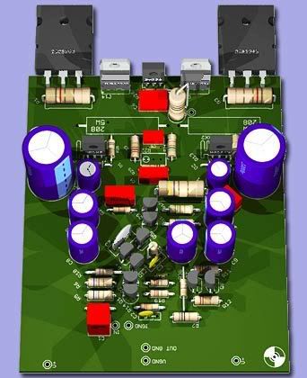
Mr B. I hope you don't mind me takeing a few liberties with my layout... It is true to your schematic for the most part, with a few small deviations... the regulators as described earlier, seperate power traces and decoupling caps for the VAS and diff pair CCS.

- Home
- Amplifiers
- Solid State
- Explendid amplifier designed by Michael Bittner, our MikeB