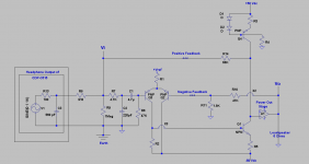
The following is a simplified schematic of a Class AB power amp using positive feedback [PF]. It is in addition to its standard overall negative feedback [ONF]. Here is its description starting from Vi and moving right to Vo:
1. The input stage is a common diff amp. It drives the second last voltage amp [LVA] which is an NPN loaded with a PNP constant current source.
2. LVA has a high voltage gain, and a high output impedance. Its output is Vo'.
3. Vo' is buffered by a pair of complementary Darlingtons. Each idles at 80 mA. Their output is Vo, and drives a 3-way loudspeaker [ADS L730]. .
4. ONF is returned to the BJT's base of the diff amp which is the inverting input. ONF gives an amplifier voltage gain of 27.
5. PF emanates at Vo' and is channeled via a 68K resistor; terminating at Vi which is the non-inverting input of the diff amp.
6. The non-inverting input circuit of the diff amp is detailed; because it is an integral part of the extent of PF that is used.
The music source is the headphone output of a SONY CDP-C515.
1. Its schematic shows it is a voltage source [Op Amp] with a 100 Ohm series resistor.
2. Another 910 Ohm resistor was added [externally] in series with the headphone output. It protects the headphone amp.
3. The net series resistance of 1000 Ohms [to the left of Vi] with the 68 K PF resistor establish a certain value for the extent of positive feedback.
This amp is very quiet at idle, and does not oscillate. This system's music sounds great from top to bottom. The bass is awesome..really.
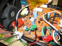
A photo of the amp's board side shows the locations which connect [via clips] the external 68K PF resistor which is housed in a pill container.
More details to follow.
1. The input stage is a common diff amp. It drives the second last voltage amp [LVA] which is an NPN loaded with a PNP constant current source.
2. LVA has a high voltage gain, and a high output impedance. Its output is Vo'.
3. Vo' is buffered by a pair of complementary Darlingtons. Each idles at 80 mA. Their output is Vo, and drives a 3-way loudspeaker [ADS L730]. .
4. ONF is returned to the BJT's base of the diff amp which is the inverting input. ONF gives an amplifier voltage gain of 27.
5. PF emanates at Vo' and is channeled via a 68K resistor; terminating at Vi which is the non-inverting input of the diff amp.
6. The non-inverting input circuit of the diff amp is detailed; because it is an integral part of the extent of PF that is used.
The music source is the headphone output of a SONY CDP-C515.
1. Its schematic shows it is a voltage source [Op Amp] with a 100 Ohm series resistor.
2. Another 910 Ohm resistor was added [externally] in series with the headphone output. It protects the headphone amp.
3. The net series resistance of 1000 Ohms [to the left of Vi] with the 68 K PF resistor establish a certain value for the extent of positive feedback.
This amp is very quiet at idle, and does not oscillate. This system's music sounds great from top to bottom. The bass is awesome..really.
A photo of the amp's board side shows the locations which connect [via clips] the external 68K PF resistor which is housed in a pill container.
More details to follow.
Attachments
Is it positive feedback, or could it be described as feed forward?
What performance characteristics are changed when you add in that 68k?
Why are you in Pass Labs?
What performance characteristics are changed when you add in that 68k?
Why are you in Pass Labs?
I would love to see some electronic guru's design a schematic for the F6 using some positive feedback for us solder slingers to experiment with. Now that I have my M2 built I would love to play with the F6 circuit that uses negative feedback and introduce some positive. Nelson says it can be done with other amplifiers as well.
Is it positive feedback, or could it be described as feed forward?
What performance characteristics are changed when you add in that 68k?
Why are you in Pass Labs?
Ans 1. The loop from Vo' to Vi in the schematic of Post #1 is most probably positive feedback, and not feedforward compensation [FFC]. FFC is explained in many articles on the internet. Its circuits are different, and have unrelated objectives.
Ans 2. The closed loop gain of the parent and the modified amp stays at 27. Vi increases after closing the Vo'-Vi loop to ~double its parent value.
Ans 3. I am familiar with DIYers in the Pass Labs Forum from interactions in past and present threads. The DIYers have shown recent interest in positive feedback after the successful introduction of F7 and it many schematic clones by DIYer lhquam. This thread can instead be in Solid State or in Everything Else Forums; provided its presence in the Pass Labs Forums fails preset criteria for its inclusion. I'll leave this issue to the Moderators.
I would love to see some electronic guru's design a schematic for the F6 using some positive feedback for us solder slingers to experiment with. Now that I have my M2 built I would love to play with the F6 circuit that uses negative feedback and introduce some positive. Nelson says it can be done with other amplifiers as well.
Unfortunately, I am not an electronic guru, and like you I also advocate experiments. A diyF6 with positive feedback will surface. One hopefully will not fear positive feedback as it maybe a barrier to experimentation.
Is it stable when the input is not connected to the headphone amp ?
The amp oscillated when the 1 K input resistor floated; because Vi quickly became equal to ~1/2 Vo'; which was excessive feedback.

The amp oscillated when the 1 K input resistor floated; because Vi quickly became equal to ~1/2 Vo'; which was excessive feedback.
The pos feedback factor depends on the source impedance - it is just the ratio of the 68k to the source impedance. As long as you have a low source impedance, the pos feedback factor (from the 68k) is low, the neg feedback factor dominates and the amp is stable.
With the source impedance becoming larger the pos feedback factor increases and when it approaches the neg feedback factor, instability starts to set in.
It is an interesting approach but you should put in an input buffer so you can set the pos feedback factor independently of the source impedance, and make sure it is always lower than the neg feedback factor.
Jan
Why are you in Pass Labs?
'Antoinel' is one of the 'scout ants' of PapaLand, constantly searching for and tasting any morsel that Papa may drop.
Positive feed-back (PFB) is the current (no pun intended) buzz-phrase right now (First Watt F7).
G
constantly searching for and tasting any morsel that Papa may drop.
Like I don't?
I have vfets and jfets ready to be buttered-up and mounted, but this PFB thing has me ready to jump ship, and swim to some unseen shore paradise...🙂
Thank you all for your comments and advice. I'll show results tomorrow which are in line with your posts' guidance.
'Antoinel' is one of the 'scout ants' of PapaLand, constantly searching for and tasting any morsel that Papa may drop.
Positive feed-back (PFB) is the current (no pun intended) buzz-phrase right now (First Watt F7).
G
now you know why a person is sole member of my ignore list
now you know why a person is sole member of my ignore list
My ignore list is at 3 people at the moment.
2 of the 3 have a chance of making their way off the list but the other one is a life time hall of fame member on the ignore list. Hahahahaha
adequate shunt resistor placed between source and R8 will do the thing
Yes will do it but will lower input impedance and still have *some* variation. I'd use a buffer.
Jan
Yes will do it but will lower input impedance and still have *some* variation. I'd use a buffer.
Jan
Don't forget he is using a headphone amp to drive it, so should be capable of easily driving a 300 Ohms input impedance.
Don't forget he is using a headphone amp to drive it, so should be capable of easily driving a 300 Ohms input impedance.
Any design should cover all possible conditions of use. Even turning the Sony off could 'raise' the impedance seen at its output terminals.
A good design has to be foolproof.
Any design should cover all possible conditions of use. Even turning the Sony off could 'raise' the impedance seen at its output terminals.
A good design has to be foolproof.
A good design is fool proof, but a custom design can be any way you want it.
I don't think Antoinel has his eye's set on any engineering awards here.
I personally wouldn't do it this way, but I'm sure Antoinel is having plenty of fun playing around with the circuit, which I assume is good thing to have if this is your hobby.
- Status
- Not open for further replies.
- Home
- Amplifiers
- Pass Labs
- Experimenting with Positive Feedback