does your toroidal come with a scheme telling you the color code?
do you have those wire labeled in some way?
just wires coming out from the transformer?
v
do you have those wire labeled in some way?
just wires coming out from the transformer?
v
Rich, the only thing that worries me with replacing those caps is the crap solder on the board, would hate to take the old caps out and not get a clean connection with the new ones.
Same here. I'd have to be 100% sure that the results are worthwhile before attempting it.
Cinemag have been run off there feet with huge orders, so if they take a while to answer emails It's not like they are avoiding anyone, they are just very..very busy.
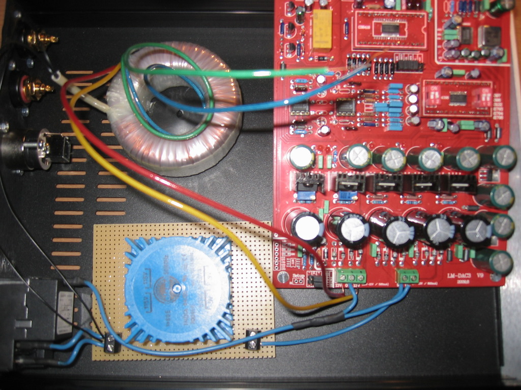
i made a new earthing cable and connected it to the 0V connectors:
i still dont understand how to connect the other wires 🙁
red and yellow is one winding and blue and green is one winding too. the black cables are for the input.
on the transformer its written like that:
primary: 230 V black-black
sec1 12v red - yellow
sec2 12v blue - green
i still dont understand how to connect the other wires 🙁
does your toroidal come with a scheme telling you the color code?
do you have those wire labeled in some way?
just wires coming out from the transformer?
red and yellow is one winding and blue and green is one winding too. the black cables are for the input.
on the transformer its written like that:
primary: 230 V black-black
sec1 12v red - yellow
sec2 12v blue - green
Sorry extr3me, I'm lost on those transformers so I can't say yes or no regarding the wires.
Someone will help you.
Hmm...so it has two secondaries each is 12v, so one wire will be 12v and one 0v or neutral. So red and blue are both the hot wires, that's all I have.
Sorry.
Someone will help you.
Hmm...so it has two secondaries each is 12v, so one wire will be 12v and one 0v or neutral. So red and blue are both the hot wires, that's all I have.
Sorry.
Last edited:
Hi Extr3me,
The easy way now is to connect red and blue and measure the AC-voltage between yellow and green.
If it is 24 V you finished the first step.
If not (0V)you connect red and green and measure again.
This way you'r supposed to end up with three wires giving
-12V, 0V and +12V.
The 0V is the two connected wires which go together to the DAC-board 0V.
The other two to the 12V's. Because you measured 24 Volts between them it means there phase is opposed to each other like they should.
Which of the two 12V's you connect to which DAC-12V does not matter because it is AC.
Maybe you try to measure this and post the results here before you connect it.
Last edited:
Sorry extr3me, I'm lost on those transformers so I can't say yes or no regarding the wires.
Someone will help you.
hey data, i dont blame u. u already helped me a lot and im thankfull for that! 😉
@gerarda am doing the steps u told me and will write again if i got something new!
Rich, the only thing that worries me with replacing those caps is the crap solder on the board, would hate to take the old caps out and not get a clean connection with the new ones.
Fair point guys, I guess the caps on the board (United Chemicon + Sanyo) are pretty respectable types. They just seem like old stock so I was considering ESR and leakage. More effective mods can be had so I'll probably leave these.
Looking at the underside I would say these PCB's have been flow soldered on a machine, then sensitive components finished by hand. Possibly machine trimmed too. Very tidy soldering despite solder and component quality.
Cheers
at blue and yellow i messure 28v when connecting red and green to each other,
so red and green goes into 0v and blue and yellow to the 13v connectors right?
edit:
how do i connect the talema transformator now?
the connectors on the board say 9v and 0v. so 0v is for a grounding connection and 9v for one of the
output-connectors from the talema right? i think it should be the + connectors shown on top of the
transformer in the middle..
Last edited:
LOL 😀 I have Pana FC's sitting here now, so tempted to give it a go, but when I removed the Muse caps after the DAC chip I couldn't get a clean signal from those points for one channel and had to take the signal from points on the DAC daughter board, so I'm a bit shy to remove those caps.
So tempting though🙄
So tempting though🙄
... so I'm a bit shy to remove those caps.
So tempting though🙄
C'mon bro take one for the team.😀
Done all that too and still silence. I'm giving it one last check over tonight and if I get no joy then the board goes back.
I get a 23V AC reading on the 15V input. Is that to be expected or does this imply something problematic?
How did you measure 23 VAC? From the 13-0-13 AC input terminal?
LOL 😀 I have Pana FC's sitting here now, so tempted to give it a go, but when I removed the Muse caps after the DAC chip I couldn't get a clean signal from those points for one channel and had to take the signal from points on the DAC daughter board, so I'm a bit shy to remove those caps.
So tempting though🙄
Do it, do it...😀
Seriously though. I can probably see myself doing this once all the other bits are done. It certainly won't decrease performance - Pana FC's are very good.
Just do the three that are part of the DAC regulation. Hot iron, plenty of flux, quick pull...😉
Hay guys!
Don't egg me on, that's a sure fire way to make sure I blow it 🙁
Maybe later 😀
Oops! I have no more good solder, pity😛
Don't egg me on, that's a sure fire way to make sure I blow it 🙁
Maybe later 😀
Oops! I have no more good solder, pity😛
Last edited:
Hay guys!
Don't egg me on, that's a sure fire way to make sure I blow it 🙁
Maybe later 😀
never touch a running system...? 😀
... i got the version DAC3_V9 too ... and I´ve got no problems at all ...
... this pcb kit was fully functional ...
And this is what i´ve read due to the last 170 pages too ... nobody having really trouble with that pcb ;-)
Good for you. Mine is also functional from the point of view of everything works.
However, the sound is distorted. I have tried different players and input sources (optical and coax). The sound is still crackling especially in the louder passage. I have emailed Gigiwork to report this problem. Let see what he will respond (at all)......
Umm...I thought it was "If it ain't broke, fix it anyway' 😉
Fred, could it be dirty power?
Maybe a different PSU
Fred, could it be dirty power?
Maybe a different PSU
Last edited:
Umm...I thought it was "If it ain't broke, fix it anyway' 😉
well then u have to improve your diy-hifi for the next 10 years, good luck 😛
well then u have to improve your diy-hifi for the next 10 years, good luck
Sorry, I missed it: does your DAC play now? Did you solve the trafo connection question?
If not, please get in contact with Rolf, be.audiophil
He offered help by phone to you.
Please don't fiddle with power transformer connections, when you don't feel sure what you're doing, please!
Franz
Sorry, I missed it: does your DAC play now? Did you solve the trafo connection question?
If not, please get in contact with Rolf, be.audiophil
He offered help by phone to you.
Please don't fiddle with power transformer connections, when you don't feel sure what you're doing, please!
Franz
hi franz,
i answered him already and will take his help 🙂
i didnt try if it works yet because i wont before im not 100% sure if everything is alright. thats why i ask here, post pics etc.
dont worry about me, until now i could finish each project without burning it 😛
- Home
- Source & Line
- Digital Line Level
- Experience with this DIY DAC ?