I imagine you would want some textbooks on electromagnetics for starters and then venture into the audio aspect of it. I rely on my limited EE schooling and Google and meld it into my audio experiences. The internet is a godsend. YMMV.
BudP probably has some book suggestions.
BudP probably has some book suggestions.
Here's some reference info I saved from rec.audio.tubes back before usenet became a wasteland. This is from around 1998, and not my words:
FYI, I purchased both books directly from Robert Wolpert -- total cost
$84. I sent a check and letter to this address:
Robert G. Wolpert
Transformer Design services
5200 Irvine Blvd. #107
Irvine, CA 92720
I think Wolpert's books are good references and worth the money if you
are interested in DIY transformers. He is a practitioner and trys to
demystify the design process.
Other books of interest to you might include 1) Reuben Lee's book on
transformers, 2) a hard to find but very good text from JPL entitled
Transformer & Inductor Design, by McLyman 3) the very contemporary set
of designer booklets available from Magnetics Incorporated -- these
include some sophisticated test and measurement results and
comprehensive design formulas, and 4) lastly, the Radiotron Designers
Handbook 4th Edition has some general summary information.
If you are mathematically orientated, the designer booklets from
Magnetics Incorporated are available free, and cover just about
everything you need to know.
Radiotron Designers Handbook vol 3 & 4. Everything you need to know about audio transformer design is covered in these two volumes. Reuben Lee is good but you cannot accept every mathematical application as correct. You will need a method for determining coil build up, mean length of turn per winding and the resultant DCR. I have one written for a TI 59 and have used it for 40 years quite successfully. Not exactly a modern device, though there are still many available.
Beyond these tools, your mind set must be centered on not designing a power transformer.
Bud
Beyond these tools, your mind set must be centered on not designing a power transformer.
Bud
I´ve maid the "finesse"trick to the clock on the upsampling module:
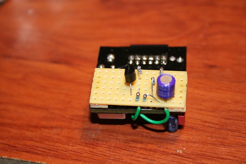
Finesse Voltage Regulator Noise!
Checked with the scope,it´s hard to see exactly,but I think it is 1-2mv less ripple.
Btw.I sold my Benchmark DAC 1 today..😛
Finesse Voltage Regulator Noise!
Checked with the scope,it´s hard to see exactly,but I think it is 1-2mv less ripple.
Btw.I sold my Benchmark DAC 1 today..😛
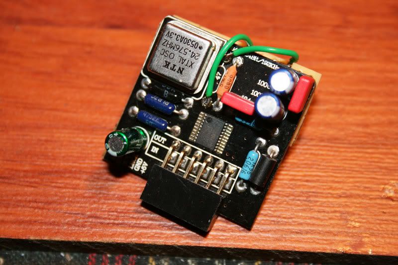
My Sample rate converter board died today (the third time it was powered up). I think I understand why it did and maybe why others are having similar problems with no sound in this DAC.
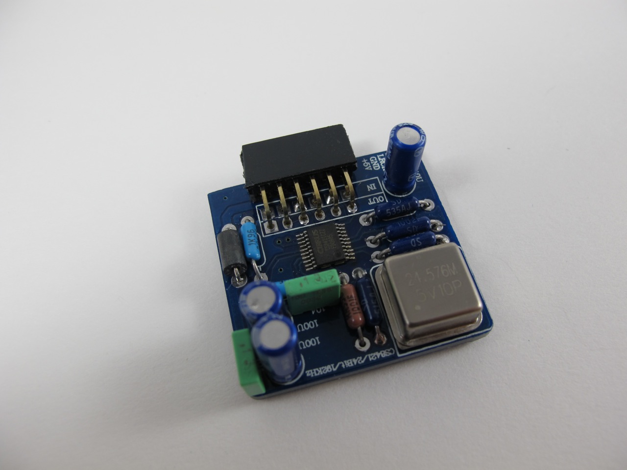
The gigawork sample rate converter board that came with my unit doe not contain any 3.3 volt regulator. This means that the entire chip is being fed 5 volts. This isn't a problem for the VL (logic voltage), but is a big deal for the VD (digital voltage). The VD line has an absolute maximum voltage of 3.5 volts which is significantly lower than the 5volts it's being force fed.
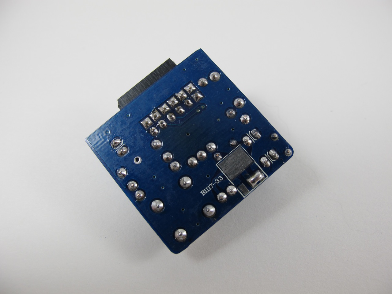
Take a look at the enclosed pictures, the part on the back side of the board is the 3.3 volt regulator, if yours is missing, you've got problems. Those of you with no sound coming out of your DAC, is this part missing?
Sheldon
The gigawork sample rate converter board that came with my unit doe not contain any 3.3 volt regulator. This means that the entire chip is being fed 5 volts. This isn't a problem for the VL (logic voltage), but is a big deal for the VD (digital voltage). The VD line has an absolute maximum voltage of 3.5 volts which is significantly lower than the 5volts it's being force fed.
Take a look at the enclosed pictures, the part on the back side of the board is the 3.3 volt regulator, if yours is missing, you've got problems. Those of you with no sound coming out of your DAC, is this part missing?
Sheldon
Wow... a solder bridge. That's bad. Did you buy it straight from Gigawork (eBay)?
I guess if you have the 3.3V regulator, then you will need that everything on digital side to be 3.3V (to avoid level-shifters).
I guess if you have the 3.3V regulator, then you will need that everything on digital side to be 3.3V (to avoid level-shifters).
Last edited:
I noticed the same thing. Gigaworks replaced my bad upsampling board with one that had the regulator attached to the back. First one did not have the regulator. How much did they save there? Couldn't be that much.
I noticed the same thing. Gigaworks replaced my bad upsampling board with one that had the regulator attached to the back. First one did not have the regulator. How much did they save there? Couldn't be that much.
They aren't saving anything when they have to replace them all 😡
Checked with the scope,it´s hard to see exactly,but I think it is 1-2mv less ripple.
You really need a spectrum analyzer for that task. You'd check the power to the chip and more importantly the spectral purity of the clock before and after adding the clamp. I don't have an RF spectrum analyzer at home, so I'm flying blind.
Sheldon
about the MCU or the CPU chip, as refered on the "so called manual"
Hello Wonderful PPL
I was wondering if anyone knows anything, like part number or kind, of the IC referred as CPU or MCU on the 5 page manual in a form of a .doc that the Chinese man send me along with my LM3 DAC.
I am talking about the apparatus that does the selection of the input via a push button, a gear that is substituted by the two jumpers in the rear of the DAC.
Since I am planing on using it separately as a stand alone DAC, I would need to have access to that selection function from the front, and I have already thought out of a 4066 quad analog switch setup, but if it is possible for the original chip to be found, why not go with it...?
regards to everyone!
angelo
I´ve maid the "finesse"trick to the clock on the upsampling module:
Finesse Voltage Regulator Noise!
Checked with the scope,it´s hard to see exactly,but I think it is 1-2mv less ripple.
Btw.I sold my Benchmark DAC 1 today..😛
Ryssen
Don't you have some heat issue for CS8421 there?
I´ve maid the "finesse"trick to the clock on the upsampling module:
Finesse Voltage Regulator Noise!
Checked with the scope,it´s hard to see exactly,but I think it is 1-2mv less ripple.
Btw.I sold my Benchmark DAC 1 today..😛
Hello Ryssen,
I would like to ask , How does this Dac compare to the benchmark Dac, In sound quality?
Thank you.
No,I don´t have a spectrum analyzer,maybee someone has one and can tesbuild the finesse..You really need a spectrum analyzer for that task. You'd check the power to the chip and more importantly the spectral purity of the clock before and after adding the clamp. I don't have an RF spectrum analyzer at home, so I'm flying blind.
Sheldon
Ryssen
Don't you have some heat issue for CS8421 there?
No,should I?
Hello Ryssen,
I would like to ask , How does this Dac compare to the benchmark Dac, In sound quality?
Thank you.
Hard to tell,was a while since I listened to the Bechmark,wich has lots of details like this one,but this one is a little more upfront,wich I like more.
O-Netics transformers
Hi
where can one get O-Netics suitable for this dac? what would be the model?
Thanks
Hi
where can one get O-Netics suitable for this dac? what would be the model?
Thanks
Hi Guys,
Didn't know my name was being taken in vain..... I do build Dac Buffer transformers. So do a number of other folks.
Major difference between my and Lundahl parts are in information retained. To use amorphous core material as Per does, you must eliminate capacitive coupling as much as possible. If you don't you get enormous FR spikes around 60 to 80 K.
The amorphous core is quite good enough for the purpose and the Lundahl products are very clear, linear, with excellent tone and transient response. They are however slightly lacking in internal note and transient gradient information. Not a bad thing.
In comparison, ours have a bit more distortion and so are slightly softer in character, but the trade off is in information density, in those small amplitude signals that provide coherent gradient information.
For those who prefer solid state sound qualities, I would strongly recommend Lundahls products. Clear, clean and sweet. For those of you who just can't get enough information, I would recommend O-Netics transformers. Clear, clean, sweet and with a fire hose of of music attached.
At these levels of performance it really is a matter of taste and I hope I have fairly portrayed the differences. Jensen is sort of in the middle and no negative connotations should be drawn about their performance either.
Bud
I'm selling my dac setup: altec Lansing transformers, relcap polystyrene caps, prp resistors. The board is wired for trafos only opamp section removed. Pcocc wiring etc. PM if interested. I'll put in for sale section but really you guys are the only ones who'd care!
If I am to use I2s from e.x Squeezebox Duett to CS4398 or the upsamplerboard ,should I also use the MLCK?
If you are using the upsampler you do not need the MLCK, the upsampler board supplies the clock. If you are not using the upsampler then the MCLK is mandatory.
Ok,thanks for the answer Bill.
Have avy one tried the CS43122 DAC?
http://www.diyaudio.com/forums/digi...new-small-diy-gigawork-dac-6.html#post2224476
Does it have voltage analogoutput?
Have avy one tried the CS43122 DAC?
http://www.diyaudio.com/forums/digi...new-small-diy-gigawork-dac-6.html#post2224476
Does it have voltage analogoutput?
for those who use 1+1:1+1 with 600 ohm primaries and also 600 ohm secondaries impedance trafos on CS4398 DAC, I would ask - wouldn't it be a better solution to use a trafo with 150 ohm primaries input impedance and a 600 ohm secondaries output impedance with the only difference that this has a ratio of 1+1:2+2 so it would amplify the input signal with 2x ?
I'm asking this , since in the cs4398 datasheet it is stated that it's output impedance is 118 ohm so I think maybe it would be a better match/solution to fed it into a 150 ohm input impedance
I'm asking this , since in the cs4398 datasheet it is stated that it's output impedance is 118 ohm so I think maybe it would be a better match/solution to fed it into a 150 ohm input impedance
- Home
- Source & Line
- Digital Line Level
- Experience with this DIY DAC ?