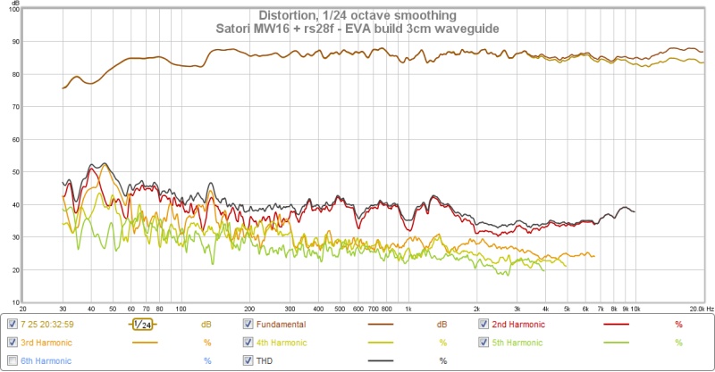
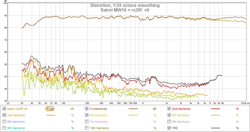
Those are excellent distortion figures, -45dB to -50dB is about as good as these drivers get. What this means is that the EVA foam is not vibrating and contributing too much to the HD. I think you mentioned you are using rubber cement as the glue between sheets of EVA. That may be key as it is viscous when dry and performs a constrained layer damping (CLD) between the layers.
I have to think about what is causing the ringing. Take a cursor and get the exact time between the ring peaks and back out the frequency. Look at freq response plot to see if that is a diffraction or resonance, or electrical DSP induced.
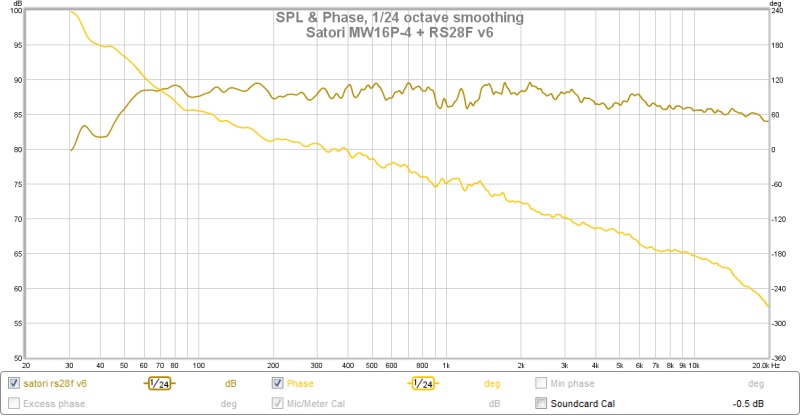
It looks like you might be able to use a tad -2 or -3dB of baffle step compensation to balance out the bass and highs. Looks very good though. Nice work.

Just a thought...
If an enclosure resonance, it could be caused by the back panel being under tension - even the CLD / layer over that will be under the same conditions and 'panel draw' (starved horse look)Will affect the adhesive thickness across the panels width.
You'd only really see the panel draw under slot lights, it might not be a lot, but it could make enough of a difference in its absorption / transmission characteristics.
EVA panels might be fine when it comes to not contributing because they have some of the same properties as membrane bass traps and the material itself has great damping.
But, what about when you want the air column inside the speaker to do work, like horns, BR, TQWT and TL. Won't the flexing bring the efficiency down unacceptably compared to stiffer materials?
But, what about when you want the air column inside the speaker to do work, like horns, BR, TQWT and TL. Won't the flexing bring the efficiency down unacceptably compared to stiffer materials?
Might be fine....EVA panels might be fine when it comes to not contributing because they have some of the same properties as membrane bass traps and the material itself has great damping.
One reason why Grubby Clarke persued PU foam - because it has most of balsa's characteristics, including going 'starved horse'' when bent round a radius un-supported.
But, what about when you want the air column inside the speaker to do work, like horns, BR, TQWT and TL. Won't the flexing bring the efficiency down unacceptably compared to stiffer materials?
I doubt 30mm of foam is going to flex too much unless the pressures are quite wild, thinner inside panels criss-cross bound with carbon tow bonded with pva could well be a cure for flex.
Outer panels skinned in fabric, paper or even very thin ply wood / obechi veneer like what they skin model plane hotwired eps foam core wings with.
jeshi and xrk971,
Study material how these filters look ringing wise when run in pure electric domain, these can be used as quality control to compare with actual acoustic real world measurements. Setup is 16bit/48kHz UCA222 USB soundcard loopback with JRiver DSP engine setting the filters and REW listening in loop, in praxis done by choosing JRiver MC 20 virtual sound device as output device into REW preferences.
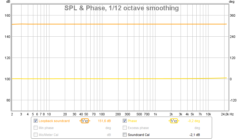
FR/Phase soundcard loopback from 2-24000Hz DSP bypassed, should not be nessesary show that group delay is ruler flat with a phase as below:
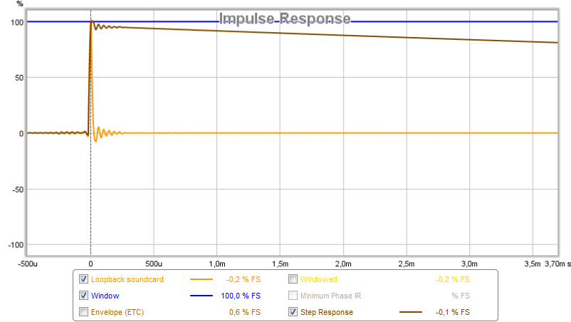
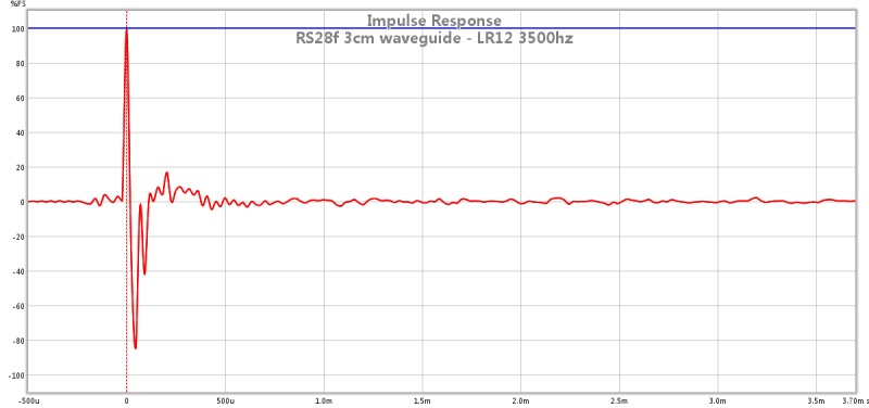
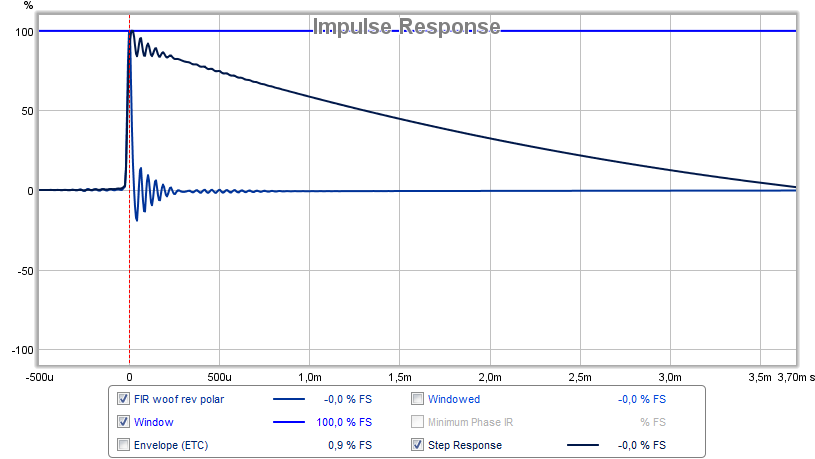
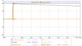
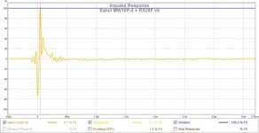
IR/SR soundcard loopback DSP bypassed, 48kHz samplerate set bandwidth high cut filter at 24kHz that LPF is reason the ringing in start of SR decay and when IR settle back to zero, soundcard analog HPF is at fair close to DC in that SR goes to 41mS before crossing zero:
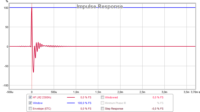
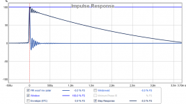
Electric loopback IR, DSP filters set bandwidth LR2 2300Hz - BW2 23000Hz as a virtual tweeter:
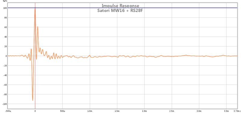
Actual tweeter measured acoustic, think is pretty nice compared above which have textbook slope and clean flat FR, where below has little falling response in top octave and wriggled FR:
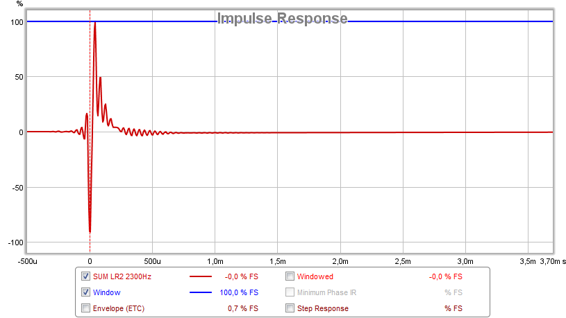
Electrical loopback IR summed, DSP filters set bandwidth BW2 40Hz - 2300Hz LR2 for virtual woofer and bandwidth LR2 2300Hz - BW2 23000Hz for virtual tweeter (tweeter polarity reversed):
Actual system sum measured acoustic, think is pretty nice compared above which have textbook slopes and clean flat FR, where below has falling response in top octave and wriggled FR:
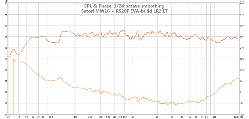
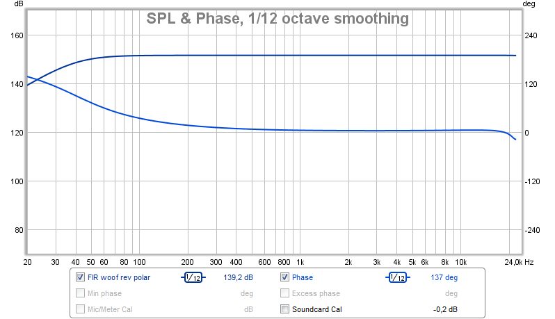
At mic point in space actual measured nice system sum FR/Phase. Phase is not as a LR2 2300Hz should reflect as pointed out in post 45, more info see next picture:
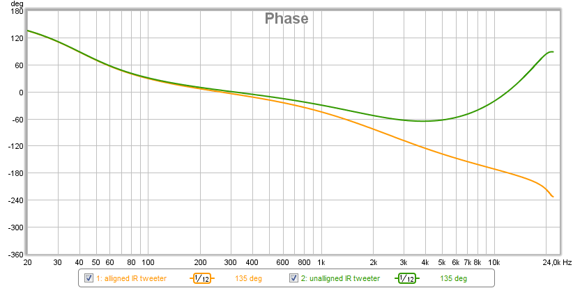
Green trace is when first IR negative going step (tweeter) is not aligned at time zero but the later positive going one is and seems REW do the math for phase based this, orange is aligned and now show correct LR2 180º phase turn centered around 2300Hz:

Electrical loopback LR2 2300Hz summed FR/Phase, for fun show FIR convolution filter added in DSP chain, filter is made in RePhase and neutralize LR phase turn:
Electrical loopback LR2 2300Hz IR/SR with above FIR filter, the harsch XO type xrk971 suggested are fair close to this performance:
Study material how these filters look ringing wise when run in pure electric domain, these can be used as quality control to compare with actual acoustic real world measurements. Setup is 16bit/48kHz UCA222 USB soundcard loopback with JRiver DSP engine setting the filters and REW listening in loop, in praxis done by choosing JRiver MC 20 virtual sound device as output device into REW preferences.
FR/Phase soundcard loopback from 2-24000Hz DSP bypassed, should not be nessesary show that group delay is ruler flat with a phase as below:
IR/SR soundcard loopback DSP bypassed, 48kHz samplerate set bandwidth high cut filter at 24kHz that LPF is reason the ringing in start of SR decay and when IR settle back to zero, soundcard analog HPF is at fair close to DC in that SR goes to 41mS before crossing zero:
Electric loopback IR, DSP filters set bandwidth LR2 2300Hz - BW2 23000Hz as a virtual tweeter:
Actual tweeter measured acoustic, think is pretty nice compared above which have textbook slope and clean flat FR, where below has little falling response in top octave and wriggled FR:
Electrical loopback IR summed, DSP filters set bandwidth BW2 40Hz - 2300Hz LR2 for virtual woofer and bandwidth LR2 2300Hz - BW2 23000Hz for virtual tweeter (tweeter polarity reversed):
Actual system sum measured acoustic, think is pretty nice compared above which have textbook slopes and clean flat FR, where below has falling response in top octave and wriggled FR:
At mic point in space actual measured nice system sum FR/Phase. Phase is not as a LR2 2300Hz should reflect as pointed out in post 45, more info see next picture:
Green trace is when first IR negative going step (tweeter) is not aligned at time zero but the later positive going one is and seems REW do the math for phase based this, orange is aligned and now show correct LR2 180º phase turn centered around 2300Hz:
Electrical loopback LR2 2300Hz summed FR/Phase, for fun show FIR convolution filter added in DSP chain, filter is made in RePhase and neutralize LR phase turn:
Electrical loopback LR2 2300Hz IR/SR with above FIR filter, the harsch XO type xrk971 suggested are fair close to this performance:
Attachments


That's nice study you did there Byrtt. Again, your electrical loop back experiments are really helpful. It shows that Jeshi's drivers are behaving exactly right. Nothing you can do about the ringing. It looks like you are using a Behringer UCA222 USB Audio interface and it works fine. I will have to get one.
thanks. I also think that the rubber contact cement laminated EVA is giving some sort of CLD effect. Great to hear that these distortion results also add data to the theory that the EVA foam vibration is working to control resonance (good vibrations) and is not contributing to the HD.Those are excellent distortion figures, -45dB to -50dB is about as good as these drivers get. What this means is that the EVA foam is not vibrating and contributing too much to the HD. I think you mentioned you are using rubber cement as the glue between sheets of EVA. That may be key as it is viscous when dry and performs a constrained layer damping (CLD) between the layers.
Nice work.
I am sure people would freak out if they saw/felt how much these speakers vibrate when playing bass. It kind of goes against current thinking, but I am still convinced that the vibration is good in this case (absorbing and damping). I wish I had access to a laser interferometer microphone to measure wall vibration. I suspect that the EVA is absorbing the sound and the damping is quickly shifting the resonance to lower frequencies, and damping the energy very quickly. So I am guessing that the walls are vibrating at maybe 10-20hz (it is a soft vibration, not a buzz feeling).
I think this is my fault. I am applying a treble high shelf boost and may have over compensated. Also I think my LT is off. I based the calculation on a box-model prediction. I will try to measure the actual Qtc and Fsc of the box and redo my LT transform.It looks like you might be able to use a tad -2 or -3dB of baffle step compensation to balance out the bass and highs. Looks very good though.
Last edited:
Electrical loopback IR summed, DSP filters set bandwidth BW2 40Hz - 2300Hz LR2 for virtual woofer and bandwidth LR2 2300Hz - BW2 23000Hz for virtual tweeter (tweeter polarity reversed):
Actual system sum measured acoustic, think is pretty nice compared above which have textbook slopes and clean flat FR, where below has falling response in top octave and wriggled FR:
Green trace is when first IR negative going step (tweeter) is not aligned at time zero but the later positive going one is and seems REW do the math for phase based this, orange is aligned and now show correct LR2 180º phase turn centered around 2300Hz:

thanks for an awesome simulation byrtt!! Really great to hear my actual IR measurements are so close to the simulation.
I think my waveguide boost is throwing off my ability to get the tweeter at the correct LR2 2300hz point. I think I have a previous alignment experiment which looked like that last phase graph. I always though LR2 should have a flat phase, but I guess it is supposed to have a gently rising phase. I will try to adjust my tweeter xo point to try to get this alignment.
I really want to try the harsch xo. I just need to get my brain wrapped around the details. Will the harsch xo work with time aligned drivers? I previously measured the actual time alignment but I can't find my notes. I will try to duplicate those. But I know that the current 3cm waveguide is near perfect time alignment without need for dsp correction.
I once mounted a small (2") driver into a 20cm cube of PU foam or fairly high density, with a hollow just big enough for the required volume (TB W2-800SL, so only 100cc or so required).
It worked ok. Best part was the majority of the back radiation seemed to be absorbed (by ear at least).
I would love to have taken some measurements of that (no mic). I was hoping for some semi cardioid nature to the experiment.
It worked ok. Best part was the majority of the back radiation seemed to be absorbed (by ear at least).
I would love to have taken some measurements of that (no mic). I was hoping for some semi cardioid nature to the experiment.
really want to try the harsch xo. I just need to get my brain wrapped around the details. Will the harsch xo work with time aligned drivers? I previously measured the actual time alignment but I can't find my notes. I will try to duplicate those. But I know that the current 3cm waveguide is near perfect time alignment without need for dsp correction.
It works fine with time aligned drivers - the delay specified is supposed to be added to already time aligned drivers. Delay equal to half the period of one cycle at the xo frequency.
Basics of Harsch XO are:
1. Set low pass on woofer as Butterworth -24dB/octave at fc (xo center frequency)
2. Set high pass on tweeter as Bessel -12dB/octave at fc (miniDSP has only "Bessel" but I think it is the second order.)
3. Set delay of tweeter to be equal to 0.5x(1/fc)
4. Set all polarities to be positive (do not flip polarity on any)
That's it. Pretty simple actually.
thanks for an awesome simulation byrtt!! Really great to hear my actual IR measurements are so close to the simulation.
I think my waveguide boost is throwing off my ability to get the tweeter at the correct LR2 2300hz point. I think I have a previous alignment experiment which looked like that last phase graph. I always though LR2 should have a flat phase, but I guess it is supposed to have a gently rising phase. I will try to adjust my tweeter xo point to try to get this alignment.
I really want to try the harsch xo. I just need to get my brain wrapped around the details. Will the harsch xo work with time aligned drivers? I previously measured the actual time alignment but I can't find my notes. I will try to duplicate those. But I know that the current 3cm waveguide is near perfect time alignment without need for dsp correction.
Welcome, its a nice build you have there and very interesting box material, thanks sharing.
Seems you thought that LR2 supposed to have flat phase and explain you haven't cared what you sum plot presented. In IRR domain seems all filters for a two way speaker higher than 1.order (BW1 phase linear when summed on axis) when summed and on axis adds distortion to phase by turning it when compare (before XO) I/O (acoustic sum) signal. xrk971 suggestion to try harsch XO type is good compromise to have a close to linear phase in XO region from IIR filters, else it seems we need FIR filters also to help get pure perfect flat phase (miniSharck can do FIR too). For info i used RePhase convolution FIR filter to correct the 360º phase turn in reality a LR4 IIR XO filter distort my phase posted at comparison thread round 2 where we talked 10F/8424 http://www.diyaudio.com/forums/full...3in-5in-drivers-round-2-a-46.html#post4397112.
Your published measurement is okay you just need to push a buttom in REW to have correct phase plot for the summed plot, FR won't react to pushing that buttom only phase will, and by this i mean don't go back to a previous alignment that showed a look more as it was supposed to because it's only a small time alignment in IR placement on time domain that makes fault. When REW do a measurement it aligns IR peak to timing point zero by itself and no problem when measuring single driver that only have one peak but a problem for LR2 that present it to a IR that go both positive and negative way and sometimes it align to the wrong one. Therefor with "Impulse" plot view window for that old measurement sum of speaker hit "Controls" icon at right side in REW and then "Estimate IR Delay", this should move your IR on time line so negative going peak align instead of positive peak, and now go back to phase plot and it show the correct absolut phase for your system and if this is true and want saved remember to save mdat once again 🙂. Learned this myself from others here at diya and another good advise is always after a measurement take the first plot look at "Impulse" window because if it show weird figures then forget this measurement and make a new one, some temporary acoustic or electric noice probably had messed with session. Below you see orange is correct timeline aligned having negative going peak correct and at green REW had set positive going peak aligned, in next picture with phase this makes quite a change and now as a LR2 in reality turn phase 180º around XO frq point the 90º turn is correctly reflected at 2300Hz. Would love to see your plot again if you try above : )
Attachments

These are great tips Byrtt. If one has only a positive main peak (since drivers are all in phase) does one still need to click "Estimate IR delay" prior to viewing phase?
These are great tips Byrtt. If one has only a positive main peak (since drivers are all in phase) does one still need to click "Estimate IR delay" prior to viewing phase?
Take answer with gran of salt but my logic says yes so the math for phase based on IR gets 100% true reflecting absolute phase. If DUT performance quality is high and environment plus gear is good think peak is so sharp that REW get it 100% aligned on the fly most times, that i notice often and then if hiting "Estimate IR Delay" one only gets the pop up message "Estimated delay is zero". Use IR alignment for summed system measurements, but for single driver measurement midranges and woofers and especially if XO filter is at place too for midranges and woofers then never use that bottom because peak is often so wide and soft that it goes wrong for REW that then align to sharpest point actual the rising start of peak instead of soft top, if alignment needed for those soft peaks do it manual toggle the arrows in the tool under "Controls".
Last edited:
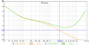
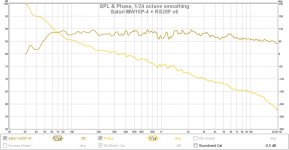
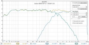
Made some adjustments to the XO and eq. I think this looks and sounds much better. Still an LR2 alignment around ~2000
frequency response and phase look flatter now.
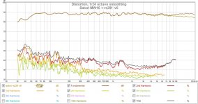
Distortion is a little better too, especially in the midrange and around the crossover point
here is the new crossover. again the waveguide makes the actual DSP XO filter and the final acoustic crossover point different.
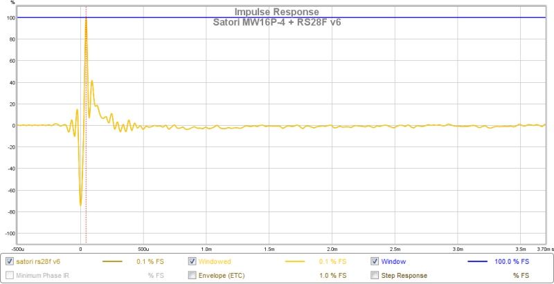
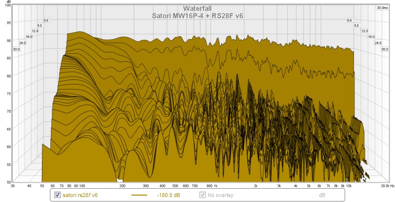
IR and CSD look about the same, but are still good
Here are the specs of the DSP (calling this v6)
rs28f high shelf 9000hz +2.5 q0.7
rs28f peak eq 11500 +3 q2
satori level -0.4db
satori peaks 1344 +6.4 q5 / 1011 -7.5 q7.9
satori peaks 142 -5.3 q3 / 121 +6.8 q2.8
satori LR2 2300hz
rs28f LR2 3000hz
LT + BW12 27hz
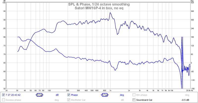
The satori has two regions of glitches. One is around 1200hz which shows up on zaphs plots and the offical FR. Mine come out a bit stronger. The other is around 130hz. Does anyone think either of these can be cleaned up with changes in the enclosure (baffle-diffraction, chamfer...)?
But with the new DSP eq and crossover the final result is very pleasing.
frequency response and phase look flatter now.
Distortion is a little better too, especially in the midrange and around the crossover point
here is the new crossover. again the waveguide makes the actual DSP XO filter and the final acoustic crossover point different.
IR and CSD look about the same, but are still good
Here are the specs of the DSP (calling this v6)
rs28f high shelf 9000hz +2.5 q0.7
rs28f peak eq 11500 +3 q2
satori level -0.4db
satori peaks 1344 +6.4 q5 / 1011 -7.5 q7.9
satori peaks 142 -5.3 q3 / 121 +6.8 q2.8
satori LR2 2300hz
rs28f LR2 3000hz
LT + BW12 27hz
The satori has two regions of glitches. One is around 1200hz which shows up on zaphs plots and the offical FR. Mine come out a bit stronger. The other is around 130hz. Does anyone think either of these can be cleaned up with changes in the enclosure (baffle-diffraction, chamfer...)?
But with the new DSP eq and crossover the final result is very pleasing.
Attachments
-
 satori-rs28f-20150727-v6-FR.jpg75.7 KB · Views: 888
 -
 satori-rs28f-20150727-HD.jpg99 KB · Views: 1,122
 -
 satori-rs28f-20150727-v6-IR.jpg61.5 KB · Views: 870
 -
 satori-rs28f-20150727-v6-CSD.jpg135.6 KB · Views: 863
 -
 satori-rs28f-20150727-v6-XO.jpg85.5 KB · Views: 892
 -
 satori-20150727-v6-noeq.jpg86.3 KB · Views: 859
Last edited:
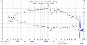
Very nice result Jeshi. These speakers must sound fantastic and I believe you have achieved your goal for them as near field monitors. Curious how much better (or worse) you will like them once the Harsch XO is put in place. The nice thing with miniDSP is that it is a simple config reload away if you don't like what you get and want to go back to your last setup. I think the 1.2kHz glitch in the Satori may be suspension related (surround-to-cone interface). Some drivers I have seen manufacturers apply a gloppy sticky surround cement at this interface. PA drivers in particular, but I have also noticed this most recently on a rubber-surround Tang Band W3-1364SA with bamboo paper cone. At the rubber roll interface, there is a non-drying tacky rubber glue/cement. The frequency response through the 1lkHz to 5 kHz range on this driver is smooth as butter. The Satori is rather expensive but I wonder if something like Permatex gasket compound (non-hardening variety) applied in a thin bead at the surround and cone interface may work?
Special sauces will be one of my next things to explore.
Special sauces will be one of my next things to explore.
Special sauces will be one of my next things to explore.
Zig 2 Way scrappers glue X..... tis good sauce😉
Very nice result Jeshi. These speakers must sound fantastic and I believe you have achieved your goal for them as near field monitors. Curious how much better (or worse) you will like them once the Harsch XO is put in place. The nice thing with miniDSP is that it is a simple config reload away if you don't like what you get and want to go back to your last setup. I think the 1.2kHz glitch in the Satori may be suspension related (surround-to-cone interface). Some drivers I have seen manufacturers apply a gloppy sticky surround cement at this interface. PA drivers in particular, but I have also noticed this most recently on a rubber-surround Tang Band W3-1364SA with bamboo paper cone. At the rubber roll interface, there is a non-drying tacky rubber glue/cement. The frequency response through the 1lkHz to 5 kHz range on this driver is smooth as butter. The Satori is rather expensive but I wonder if something like Permatex gasket compound (non-hardening variety) applied in a thin bead at the surround and cone interface may work?
Special sauces will be one of my next things to explore.
I haven't talked much about the sound of my speakers yet, but they really are excellent. The LR2 integration of the rs28f with the satori is sublime and the extension of the rs28f is so smooth yet detailed. Really does succeed as a high-end near-field monitor. I could not be happier with my driver choices. I am still tweaking the box and baffle though. Part of the problem is my removable front baffle which is leaking a bit on heavy bass. For some reason it doesn't seem to show up in the measurements (maybe in the elevated <60hz distortion?). But the removable baffle is important right now since I really want to experiment with different baffle arrangements. The removable baffle will also allow me to do a 10f /satori baffle with the same box. I think once the neoprene arrives and I can experiment with lining the inner walls to "mass load" them and use a neoprene gasket to seal the removable baffle, I suspect it will take it to another level.
One of my motivations for choosing the satori and rs28f was to get as high quality drivers as I could (without going crazy: scanspeak illuminator, accuton, seas excel...). I don't have a lot of space in my apartment, so there is not so much room for experimenting with different large drivers. Actually 5th-element helped me alot in choosing the Satori MW16p-4. http://www.diyaudio.com/forums/mult...8a-sb15-sb17-satori-ss8530-3.html#post4020087
I was thinking that the satori would give me as close to perfect a mid-woof and I could augment with my subwoofer (below 40hz) and play with different tweeters/fullrange on top. But the RS28f is exceeding my expectations. Might want to try a scanspeak Illuminator R3004/602010 or D3004/602010 tweeter someday, but no rush.
I don't think I will alter/modify the satori though. I don't want to do anything non-reversible. The 1200hz dips/distortion are not really audible/offensive. I will keep playing with different box/brace/baffle ideas to see if anything can help that 1200hz breakup, but I doubt it. When my 10f/8424 arrives I can crossover with the satori in the 400-700 range (like your 10f/rs225 FAST) and avoid that satori breakup/distortion point completely. Should be interesting...
That Satori is pretty nice... and it integrates well with the RS28F, which is quite the value. Your little EVA foam monitors exhibit some amazing measurements. I don't believe you will see as clean a HD plot from a rather expensive Genelec 8000 series monitor.
- Home
- Loudspeakers
- Full Range
- EVA foam for performance speaker enclosures