oh nice thank you haiqu I think I can do that on the layout sure, this resistor is also 100R? I'm going to do the changes then later will post layout to see if I did it correctly 🙂
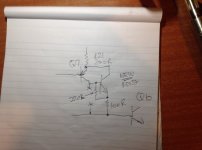
No, that resistor is 220R, just like it says on the paper.
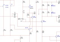
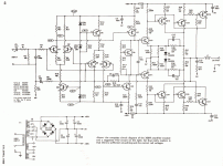
The points marked X are just to show where the collector of Q9 was lifted, they don't connect to anything now.
This mod was designed for the ETI-480 and I notice that the ETI-466 now has a balanced design in the phase splitter section. I did the above modification to one ETI-466 and it sounded better, but maybe the top half could also be done similarly. I will leave that as an exercise for you to work out. 🙂
In any case you could add it to the board design, even if it isn't used.
Hi haiqu
when you get a time see the changes let me know if this is correct, I was able to adjust to 1V voltage drop across one of the fuses with the 10R resistors
Nope. 220R should go between E-B on Q18. Q18 base goes to Q9 collector.
Why do you want insert a Sziklay pair instead of a simple common emitter transistor ? The stability of the amplifier will suffer. It is a risky bussines.
Why do you want insert a Sziklay pair instead of a simple common emitter transistor ? The stability of the amplifier will suffer. It is a risky bussines.
Well, firstly it isn't a Sziklai pair. That 220 ohm resistor isn't part of the Sziklai, and besides I've had this circuit since before Sziklai's patent. But to answer your question, it sounds better and doesn't add any instability at all. I ran a pair of ETI-480 100W amplifiers configured this way for 35 years, and I assume the guy who insisted on buying that amp from me in 2011 is still running it today.
The attribution for this idea should be added here. It was devised by Rowan McCombe, who used to design amplifiers for Allen Wright. He was a mad genius.
Apart from the fact its a Szikai pair (aka CFP)....Compound vs DarlingtonWell, firstly it isn't a Sziklai pair.
Its a standard enhancement to Darlington pairs and Sziklai pairs used everywhere! It doesn't stop it being a pair.That 220 ohm resistor isn't part of the Sziklai
In 1952 and 1953?and besides I've had this circuit since before Sziklai's patent
CFP's have stability issues that may bite you, this is well known - a tendency to parasitic oscillation.
Its a standard enhancement to Darlington pairs and Sziklai pairs used everywhere! It doesn't stop it being a pair.
In 1952 and 1953?
CFP's have stability issues that may bite you, this is well known - a tendency to parasitic oscillation.
Patent lookup failed me there. It was 1956, US patent 2,792,870. I looked that up and was transported to a different patent, dated 1978. Possibly earlier in his home country
In any case, I've never had any stability issues with it.
@Mark Tillotson
BTW there was a far better mod for the ETI-480, but it doesn't apply to the ETI-466. Take the 27 pF compensation cap off Q5 collector and run it direct to the output node. The noise drops quite dramatically. That can be credited to an idle comment by Cherry that I read someplace.
Edit: Found it. EW & WW Jan 1995.
Last edited:
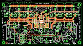
Have layout PCB for ETI477 .🙂
Ah, the Tilbrook Series 5000 FET amp. That one came out after I went into the computer industry so I never built it. I've read mixed reviews about it; evidently it needed some work, but considering the newness of FET amplifiers in Australia at the time it was a reasonably good attempt.
hi haiqu
Last question "I hope so" 😛, on the Q18, "the mod transistor" does not net to be placed on the main heat sink like Q7 and Q9 are? cause Q8 is the one that is thermally sensing bias already right?
That's right. It doesn't need to go on the heatsink.
hi haiqu
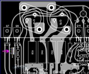
can you take a look at the mod on the layout to see if I got it right?
Sorry, too hard. All the parts have different number from the original circuit. 🙂
oh ok what I did is use the original ID's from the original schematic to multisim I'm gonna attached here on this post 🙂 "to documented here"
Attachments
Last edited:
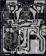
Sorry, it's just too different, all the resistors have different numbers. I'll just have to trust you. 🙂
Since you haven't produced the PCB yet, here's the circuit for the other half. I mentioned above that since it's a balanced circuit (unlike the ETI480) both halves could be modified. You might as well do both! Those big resistors might need to be shifted a bit though.

Since you haven't produced the PCB yet, here's the circuit for the other half. I mentioned above that since it's a balanced circuit (unlike the ETI480) both halves could be modified. You might as well do both! Those big resistors might need to be shifted a bit though.
Attachments
- Home
- Amplifiers
- Solid State
- ETI-466 300W Amplifier