I can do that sure, and you right I need to space them out ok, thanks later I will post after done 🙂
regards
Juan
regards
Juan
Attachments
Last edited:

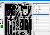
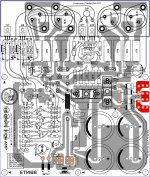
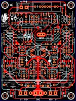
ETI 466 with mod
Hi, for purpose of documentation here is the layout with both mods that can be used or bypassed for original circuit by J1 and J2 jumpers selection and then components not been populated, Q18 collector is connected to emitter of Q9, R49 = 220 is connected to base and emitter of Q18, the base of Q18 is connected to collector of Q9 and collector of Q9 is not connected to emitter of Q8 and base of Q11 because of the J2 that is original setting with no mod in use, R50 =100R is connected to emitter of Q18 by the jumper J4 now R50 is connected to Q8 emitter and Q11 base the same scenario would be to Q19 = BD139, R53=220R and R54 = 100R I hope I got it right, sorry for the bad grammar English is my second language 😛
Hi, for purpose of documentation here is the layout with both mods that can be used or bypassed for original circuit by J1 and J2 jumpers selection and then components not been populated, Q18 collector is connected to emitter of Q9, R49 = 220 is connected to base and emitter of Q18, the base of Q18 is connected to collector of Q9 and collector of Q9 is not connected to emitter of Q8 and base of Q11 because of the J2 that is original setting with no mod in use, R50 =100R is connected to emitter of Q18 by the jumper J4 now R50 is connected to Q8 emitter and Q11 base the same scenario would be to Q19 = BD139, R53=220R and R54 = 100R I hope I got it right, sorry for the bad grammar English is my second language 😛
Attachments
Last edited:
hi haiqu if all in order I can order a few PCB then order the parts, did you see the mods are they correct? I need to be sure all is right before order, I speed time on this good reading here
ETI-466 Amplifier Technical Review
ETI-466 Amplifier Technical Review
hi haiqu if all in order I can order a few PCB then order the parts, did you see the mods are they correct?
I'm not going to try to check it. As the designer of the PCB it's your responsibility to ensure it's right. But I can tell you how I do that ... just check each trace, point to point, against the circuit. Then check it again. 😀
thanks I this is a lot simpler than this one I did but as we know we always double and double check till is 100% right 🙂 you right it is me to check agree 😉
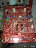
this picture is one of my work a lot complicated
Greenamp PCB V1.2 Mr. thimios tested good
this picture is one of my work a lot complicated
Greenamp PCB V1.2 Mr. thimios tested good
Attachments
Sweet! I always mess something up when I make PCBs. I guess it's because I started with bitumenous paint, even moving to Letraset was a big jump. Then I used transparent graph paper and a bubble jet printer. But designing on a computer? Arrgh!! Every time I've sent gerber files to a PCB manufacturer there have been errors. I made one 10W RF amplifier twice and it was still wrong. So if I don't trust myself, you shouldn't trust me either. 8^]
" shouldn't trust me either. 8^]" hahahaha 😛
is ok haiqu I'm going to continue check bugs on the PCB and if order I'll keep posting on this section how it goes good day 🙂
regards
Juan
is ok haiqu I'm going to continue check bugs on the PCB and if order I'll keep posting on this section how it goes good day 🙂
regards
Juan
no i had not gone down that route, just to even out the power distribution - in theory at least !
- Home
- Amplifiers
- Solid State
- ETI-466 300W Amplifier