LME49713
Hi Everyone,
A Current Feedback Opamp requires a specific value of feedback resistor. Usually 1.2k to 1.5k ohms. They also work better for audio in the inverting configuration. It is the best sounding audio opamp I have used but only where proper HF layout and power supplies are used and a low value input resistor can also be used.
Other wise the LME49710 is the next best choice and since it is a VFB opamp it is a little easier to implement. However it still requires proper HF layout and power supplies or it will oscillate.
I can promise you that if you can make these devices work in your designs then you will be more than happy with the sound quality. We have had a lot of people/staff (one hard core tube guy) listen to these devices in my prototype designs and we had 100% agreement on the improvement in sound quality over other opamps that have been around for quite awhile.
Big note however...The metal cans ALWAYS sound better than the plastic packages and you should NEVER use 4815/4915 three terminal power regulators in any high quality audio designs.
Best "Out of Work in SI Valley" Regards,
audioman54 / Mark
nagaesan said:
Next Friday night and Saturday afternoon, I hold DAC audition party.
Hi nagesan,
Can you report on your audition party?
Thanks,
Dave
Diy buddies do you think it is possible or worth it change an ES9006s present in a little 7.1 soundboard (Samsung BD-P2500 bluray player) for a ES9008S ? Will it be pin and firmware compatible ?
TT
TT
Sabre I2C read
Hi, all!
Has anyone succeeded to do a I2S read (i.e. registers 28-31)?
Datasheet does not describe reading, only write. Write works flawlessly. For write (register, value...) has to be sent, but what for read? Is it register expected before?
Thanks,
Matej
Hi, all!
Has anyone succeeded to do a I2S read (i.e. registers 28-31)?
Datasheet does not describe reading, only write. Write works flawlessly. For write (register, value...) has to be sent, but what for read? Is it register expected before?
Thanks,
Matej
Re: Sabre I2C read
Hi Matej,
Here is the sequence for a read
Start--->0x90(write)--->0x1C(Reg28)--->Start--->0x91(read)-----> (read the byte)------>Stop
You must first write to the Sabre the address you want to read.
Hope this helps.
Dustin
matejS said:Hi, all!
Has anyone succeeded to do a I2S read (i.e. registers 28-31)?
Datasheet does not describe reading, only write. Write works flawlessly. For write (register, value...) has to be sent, but what for read? Is it register expected before?
Thanks,
Matej
Hi Matej,
Here is the sequence for a read
Start--->0x90(write)--->0x1C(Reg28)--->Start--->0x91(read)-----> (read the byte)------>Stop
You must first write to the Sabre the address you want to read.
Hope this helps.
Dustin
glt said:Dustin, any info on how to get the datasheet? Thanks.
I believe you have to go through the chip distributor. (Brain Shaw in the US)
Thanks
Dustin
Hi,
I have some Q,
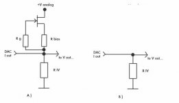
about Sabre ES9008 I-outputs :
Are they Current Source Output or Current Sink Output type?
*
Which one of theese two diagrams, I uploaded
shoud be better for the passive I-to-V conversion?
*
Which value is the lowest value of passive R iv that I could apply,
and not to damage dac chip?
Is the lower value of RIV lowering the distorsion for ES9008, same like in
for instance pcm63 and tda1541 dacs?
Or not?
*
I put, just for the test 1K (at each dac Iout, each -,+... )
the chip remain the just slight warm...
*
could someone answer please?
thanks
I have some Q,
about Sabre ES9008 I-outputs :
Are they Current Source Output or Current Sink Output type?
*
Which one of theese two diagrams, I uploaded
shoud be better for the passive I-to-V conversion?
*
Which value is the lowest value of passive R iv that I could apply,
and not to damage dac chip?
Is the lower value of RIV lowering the distorsion for ES9008, same like in
for instance pcm63 and tda1541 dacs?
Or not?
*
I put, just for the test 1K (at each dac Iout, each -,+... )
the chip remain the just slight warm...
*
could someone answer please?
thanks
Attachments
Hello Dustin
A question on the ES9008: Does the selection of either slow or fast rolloff work both with SPDIF and I2S inputs?
My setup with SPDIF-input somehow seems to be stuck to slow rolloff.
Kurt
A question on the ES9008: Does the selection of either slow or fast rolloff work both with SPDIF and I2S inputs?
My setup with SPDIF-input somehow seems to be stuck to slow rolloff.
Kurt
Re: Re: Sabre I2C read
Thanks, Dustin. It works!
My setup is 24.576Mhz clock, I2S input , SPDIF source from HK HD970 CD (most likely 48kHz).
Read DPLL_NUM (MSB-LSB) = 0x20 0x00 0x4C 0x00
If I use equation from datasheet I get strange results... however if I use the following equation:
DPLL_NUM / (2^32) * 24 576 000 / 64
I get 48 001.7395 😀
Is there an error in datasheet?
Matej
dusfor99 said:
Hi Matej,
Here is the sequence for a read
Start--->0x90(write)--->0x1C(Reg28)--->Start--->0x91(read)-----> (read the byte)------>Stop
You must first write to the Sabre the address you want to read.
Hope this helps.
Dustin
Thanks, Dustin. It works!
My setup is 24.576Mhz clock, I2S input , SPDIF source from HK HD970 CD (most likely 48kHz).
Read DPLL_NUM (MSB-LSB) = 0x20 0x00 0x4C 0x00
If I use equation from datasheet I get strange results... however if I use the following equation:
DPLL_NUM / (2^32) * 24 576 000 / 64
I get 48 001.7395 😀
Is there an error in datasheet?
Matej
Javin5 said:Hello Dustin
A question on the ES9008: Does the selection of either slow or fast rolloff work both with SPDIF and I2S inputs?
My setup with SPDIF-input somehow seems to be stuck to slow rolloff.
Kurt
Strange, both options work for the the SPDIF and I2S modes...
Sorry I wish I had a better answer.
You really should be able to jsut program the regsiter that contains the bit to control fast/slow rolloff.
Thanks
Dustin
Re: Re: Re: Sabre I2C read
Hi Matej,
Possibly, but I am not sure. I will try to remeber to check it out tommorow at work. I know that there is a /64 for the I2S mode, but not for the SPDIIF... (or vice versa, I will have to go through it again).
Thanks
Dustin
PS good so see you got it working. I didn't know if anyone would use the DPLL_NUM for anything, but I thought I might as well put it in there anyways.
Thanks
Dustin
matejS said:
Thanks, Dustin. It works!
My setup is 24.576Mhz clock, I2S input , SPDIF source from HK HD970 CD (most likely 48kHz).
Read DPLL_NUM (MSB-LSB) = 0x20 0x00 0x4C 0x00
If I use equation from datasheet I get strange results... however if I use the following equation:
DPLL_NUM / (2^32) * 24 576 000 / 64
I get 48 001.7395 😀
Is there an error in datasheet?
Matej
Hi Matej,
Possibly, but I am not sure. I will try to remeber to check it out tommorow at work. I know that there is a /64 for the I2S mode, but not for the SPDIIF... (or vice versa, I will have to go through it again).
Thanks
Dustin
PS good so see you got it working. I didn't know if anyone would use the DPLL_NUM for anything, but I thought I might as well put it in there anyways.
Thanks
Dustin
Zoran said:Hi,
I have some Q,
about Sabre ES9008 I-outputs :
Are they Current Source Output or Current Sink Output type?
*
Which one of theese two diagrams, I uploaded
shoud be better for the passive I-to-V conversion?
*
Which value is the lowest value of passive R iv that I could apply,
and not to damage dac chip?
Is the lower value of RIV lowering the distorsion for ES9008, same like in
for instance pcm63 and tda1541 dacs?
Or not?
*
I put, just for the test 1K (at each dac Iout, each -,+... )
the chip remain the just slight warm...
*
could someone answer please?
thanks
Hi Zoran,
THE output looks like a voltage source with 781.25 Ohm output impedance. "Current mode" is simple when you put the output to a virtual ground and some level (we use 1.65V) then therefore use the current though the 781.25 Ohm in a IV stage. I is not a typical "current source" or "current sink" like the other chips you mention. You could short the output of the chip to ground or AVCC without damaging the chip.
Hope this info helps
Thanks
Dustin
Hi Dustin,
thanks for answering...
It is from help to me.
*
I designed open topology, so I have Vref of 3.3V analog supp. for each channel,
and also Vref of 1.65V in case of using standard OP IV conn.
but passive R-IV, ball. tube out, SE output transformer is an option too,
as well as current buffer...
*
Do You have any experiance or idea, how low can I go with passive R
(because I need lower Vout before tube stage, gain of the tube stage will be probably
about 15 times... So it will be nice to have about hundered mV after R iv).
*
Thanks
🙂
I have been using the DPLL# feature to get the sample rate for a while now. Its working fine for me. 🙂
http://www.twistedpearaudio.com/forum/default.aspx?g=posts&m=2842#2842
Cheers!
Russ
http://www.twistedpearaudio.com/forum/default.aspx?g=posts&m=2842#2842
Cheers!
Russ
Zoran said:Do You have any experiance or idea, how low can I go with passive R
(because I need lower Vout before tube stage, gain of the tube stage will be probably
about 15 times... So it will be nice to have about hundered mV after R iv).
*
Thanks
🙂
You can simply use a resistor to AGND or any buffered voltage from AGND to AVCC.
There is nothing more to it. 🙂
If you use AVCC/2 then your DAC will not have to sink any current through your R when idle.
Cheers!
Russ
Hello Russ !
Considering the I/V conversion, what 's value for Riv that gives the 'sweet spot' (lowest DNR ?) ?
Thanks
R.C.
Considering the I/V conversion, what 's value for Riv that gives the 'sweet spot' (lowest DNR ?) ?
Thanks
R.C.
Hi Dusfor99 and Russ,
To add to the previous question from Ciu
I also want to use the ES9032 converter for measurements. Is the distortion reduced if I put 4 da converters in parallel but not feeding it the same signal, but every next converter delay the input signal one or more samples. Distortion is then perhaps spread a bit more? Or is -120 db the absolute bottom you can reach.
I also heard that somebody cooled chip with peltier element. Is that producing lower distortion (at least leakage will be better, but is distorion also better)?
Are there other hints or ways to reduce distortion?
Thanks for info
rab said:
I also heard that somebody cooled chip with peltier element. Is that producing lower distortion (at least leakage will be better, but is distorion also better)?
Thanks for info
We listened to a peltier cooled buffalo for a short time, the sound was clearer, but I think they call these thermal distorsions, you cannot measure them at the moment, these seem to be inherent to solid state. I don't know anything about it, I have just heard it, the improvement, and for the same reason I use batteries without regulators. To really implement a peltier is a bit tricky because of condensate, but we can use a normal cooling element, as big as possible.
regards
Andre
Rab, if you add delayed samples of a signal, you are changing the frequency response. If you are able to accurately compensate for that, or if flat response to 20 kHz is unimportant to you, then you could potentially obtain somewhat lower distortion, but only if the DAC-errors were uncorrelated. And you would need an absolutely outstanding IV and output stage with distortion and noise probably around -140 dB or so.
Kurt
Kurt
- Home
- Source & Line
- Digital Line Level
- ESS Sabre Reference DAC (8-channel)