Dougie085 said:But then that bypasses the DSD support of the DAC. And if you want to do that you can just feed the DAC SPDIF or something.
absolutely 😀 that is what I want to do.
Question for Russ: how does the S/PDIF buffer achieve 75 ohm of input Z? As is R13 can not determine the input Z of the circuit, but perhaps I'm wrong.
I hope it's not too late to correct this.
I hope it's not too late to correct this.
sidiy said:Question for Russ: how does the S/PDIF buffer achieve 75 ohm of input Z? As is R13 can not determine the input Z of the circuit, but perhaps I'm wrong.
I hope it's not too late to correct this.
Hi,
I have never implemented that circuit before, but I saw it in the demo board schematic, so unless there is an error in the schematic, I assume it works ok. 🙂
I Actually do think the impedance of the circuit is 75 ohms, at least at the working frequency.
Maybe someone more familiar with this input buffer can chime in.
Cheers!
Russ
sidiy said:Question for Russ: how does the S/PDIF buffer achieve 75 ohm of input Z? As is R13 can not determine the input Z of the circuit, but perhaps I'm wrong.
I hope it's not too late to correct this.
It's OK. The incoming signal 'sees' a 75 ohm impedance into the high impedance node of the comparator. It will correctly terminate and will not reflect any energy back into the 75 ohm cable impedance.

Please correct me if I'm wrong.
Then the source sees 75Ohm + something (high) to ground. Which means a lot of reflections back into the source.
rossl said:
It's OK. The incoming signal 'sees' a 75 ohm impedance into the high impedance node of the comparator.
Then the source sees 75Ohm + something (high) to ground. Which means a lot of reflections back into the source.
sidiy said:Please correct me if I'm wrong.
Then the source sees 75Ohm + something (high) to ground. Which means a lot of reflections back into the source.
Hi Sidly,
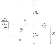
Yes you are right this circuit will not do a true 75 Ohm load to terminate the SPDIF line. It was used since it worked (All the time) . Now that you have brought it up, here is a properly done circuit.
Attachments
dusfor99 said:
Hi Sidly,
Yes you are right this circuit will not do a true 75 Ohm load to terminate the SPDIF line. It was used since it worked (All the time) . Now that you have brought it up, here is a properly done circuit.
Thanks Dustin, that looks much more conventional. 🙂
I just simulated the previous circuit, and was about to post. 🙂
Fortunately there is plenty of time to make the change.
Cheers!
Russ
Hi Dustin,
Indeed we'd be in deep trouble if that type of circuit would not work. Every CDP needs a data slicer afterall 😀 (this because despite using NRZI coding, targeted to eliminate the DC content, the RF signal from the laser diode still 'rides' on a varying level of DC)
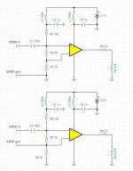
I drawed quickly two alternatives. Just a note on the bias through R2 or R7: the voltage drop across them, mainly determined by R3 and respectively R8, must be sensibly higher than the hysterezis of the comparator.
I'm using the second one in one of my DACs, inspired from the demo-board of the PMD100 digital filter.
Hope it helps, cheers!
Indeed we'd be in deep trouble if that type of circuit would not work. Every CDP needs a data slicer afterall 😀 (this because despite using NRZI coding, targeted to eliminate the DC content, the RF signal from the laser diode still 'rides' on a varying level of DC)
I drawed quickly two alternatives. Just a note on the bias through R2 or R7: the voltage drop across them, mainly determined by R3 and respectively R8, must be sensibly higher than the hysterezis of the comparator.
I'm using the second one in one of my DACs, inspired from the demo-board of the PMD100 digital filter.
Hope it helps, cheers!
Attachments
sidiy said:Please correct me if I'm wrong.
Then the source sees 75Ohm + something (high) to ground. Which means a lot of reflections back into the source.
No, I'm sorry, I disagree with your statement. (grin)
The circuit didn't reflect back to the source. That is why it worked. 😀
The term (+ something (high) to ground) is a high impedance in parallel with the 75 ohm.
The incoming AC coupled RF signal doesn't really care about it.
RF signals don't care about 'ground' in general. That is why they are so hard to conceptualize. They will leave the circuit board and travel through the air at a whim. 😀
The terminating impedance was close enough. +/- 10% is usually close enough.
I wouldn't have done it that way, but it was good enough and it worked.
You can't argue with that. 😀
Meh as long as it works and sounds awesome 🙂 I really can't wait to see how you think this DAC compares to the WM8740 that the Opus uses.
rossl said:
The term (+ something (high) to ground) is a high impedance in parallel with the 75 ohm.
Indeed it would work with (just about) any value for R13 without any reflections. 😀 And I won't argue that 😀
Keeping in mind that the DAC is virtually immune to external jitter, I'd suggest keeping S/PDIF input simple and functional.
rossl said:
That looks pretty cool, but I can't seem to find a distributor that has them in stock... So might want to find something more available.
Where would you propose sourcing them?
It looks like you can order some directly from Maxim.
or:
http://www.newark.com/68K9424/semic...ATED-PRODUCTS-MAX3280EAUK-T&_requestid=118439
Newark has 16000 in stock!
or:
http://www.newark.com/68K9424/semic...ATED-PRODUCTS-MAX3280EAUK-T&_requestid=118439
Newark has 16000 in stock!
Spartacus said:Keeping in mind that the DAC is virtually immune to external jitter, I'd suggest keeping S/PDIF input simple and functional.
Simple and functional: a 75 ohm terminating resistor, a MAX3280 in a SOT-23-5 package, and a bypass cap for the little guy.
😀
rossl said:
Simple and functional: a 75 ohm terminating resistor, a MAX3280 in a SOT-23-5 package, and a bypass cap for the little guy.
😀
You think there should also be a coupling cap?
The coupling cap was required in the comparator circuit because the comparator action operated at 1/2 VCC.
Where is the SPDIF coming from, inside the box or outside?
The MAX part has a -7V to +12V Common-Mode range.
The SPDIF + doesn't actually need a coupling cap and the SPDIF - on the cable doesn't need to be tied to ground. UNLESS it will violate the common mode range.
If there is a chance of the common mode range being violated, then an input signal transformer would solve the problem.
Well my goal is to make a module that will be flexible. So I don't want to assume that SPDIF is coming from inside or outside. Or even that it is TTL level or 500mv.
Signal transformer is certainly an option, but raises costs, but it does have the benefit of galvanic isolation.
mulling it over.
Signal transformer is certainly an option, but raises costs, but it does have the benefit of galvanic isolation.
mulling it over.
I just looked at the block diagram of the ESS Sabre and realized it does a DSD-PCM-downsampling before upsampling again. Obviously the semiconductor industry still is less fond of DSD than the music industry. What DACs are there that have true DSD (no change of sample rate)?
- Home
- Source & Line
- Digital Line Level
- ESS Sabre Reference DAC (8-channel)