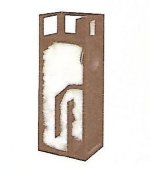
Are there any drawings for the ESS TL enclosure? I've searched the web but could never find anything.
Attachments
Last edited:
If you can get the external height and depth of that picture it’s easy to make 2d reverse engineered plans. Easier would be to design one from scratch with a good driver.
There is a big difference between thinking that age implicitly causes a lower functioning, and actually not performing at our best because of an attitude change I have discovered.
'Letting go', resigning, and relinquishing control because of a number is a big mistake, and evidence for that is all around; walking corpses.
'Letting go', resigning, and relinquishing control because of a number is a big mistake, and evidence for that is all around; walking corpses.
If you can get the external height and depth of that picture it’s easy to make 2d reverse engineered plans. Easier would be to design one from scratch with a good driver.
I wouldn't want to copy that exactly since I would use a different woofer (BP102).
I take it Hornresp would work? I've never learned how to use it 😕
If you can get the external height and depth of that picture it’s easy to make 2d reverse engineered plans. Easier would be to design one from scratch with a good driver.
Just make sure you try to stay true to the dampening methodology, unless you intend to improve upon it, or customize, but not replicate it....
I went through some paperwork tonight and found these... I scanned the original ESS Tower setup document for anyone that is interested... I learned there is a second fuse in the Heil (ah-HA)
An externally hosted image should be here but it was not working when we last tested it.
An externally hosted image should be here but it was not working when we last tested it.
An externally hosted image should be here but it was not working when we last tested it.
An externally hosted image should be here but it was not working when we last tested it.
An externally hosted image should be here but it was not working when we last tested it.
An externally hosted image should be here but it was not working when we last tested it.
I went through some paperwork tonight and found these... I scanned the original ESS Tower setup document for anyone that is interested... I learned there is a second fuse in the Heil (ah-HA)
I put all these in a PDF...
Attachments
Here is the original scanned document... It should be a tad clearer than the one "kec" uploaded. (Still learning how to use "DROPBOX")Dropbox - ESS AMT-1 Tower - Setup and Precautions.pdf - Simplify your life
Hi Pelanj,
How are you coming along with your adapters?
Have you settled on 50x30, or 60x40?
Also, how are you designing the rest of your horn? All the calculators I have found work only with square throats, but the mouth of your adapter (which will connect to the throat of the actual horn) is rectangle in shape. How are you planning to fit the horn to your adapter and what are you using to design the rest of your horn with?
I'm asking because I can't find a calculator that calculates the boards you need to cut for a horn that can calculate based off a rectangle throat - they all work on square throats only.
I really love the idea of experimenting with the uTrynergy but in place of the tweeter using the Heil, but the calculator Xrk used for that project only works with square throats as well.
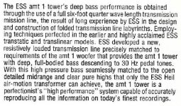
Hi thermcul, I have not printed anything since post 102. I had some failed prints and I entered the dangerous zone of printer tweaking. Almost ready now to print the 50x30 adapter. If the inner dimensions will be perfect, I will release both 50x30 and 60x40 models. I also got delayed by the idea of incorporating a mount for 3FE22 driver as midrange into the model, so that one could be mounted on each half.
For the horn front, I plan to make my own Excel sheet to calculate the angles. If I fail, I will model the horn in 3D and measure🙂
For the horn front, I plan to make my own Excel sheet to calculate the angles. If I fail, I will model the horn in 3D and measure🙂
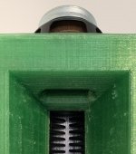
My nozzle was clogged, so I installed a 0.5 mm nozzle for faster prints. I now printing shield frames. Once I get my Al bed carrier, I will continue with this project. The acrylic holder is bending and I cannot level the bed properly for larger prints.
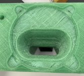
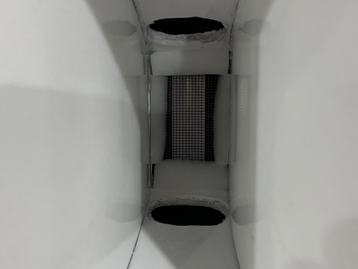
I tested new material - recycled PET (G?). It needs higher temperature, but it feels stronger than regular PETG. This is a test print for correct sizing of the 3FE22 mounting interface. I need to dismount the speaker from another project tomorrow.
Attachments

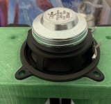
It is actually recycled PET, not PETG. So in fact, recycled soda bottles🙂 This will be my material of choice for speaker projects (if I can make it print reasonably fast and clean) as it seems to be tough as hell.
Here is my test print. It needs to be printed in two parts, the 3FE22 mounting surface looks ugly, my printer is not yet tuned to make nice bridges with this material. I tried to turn on the fan, but it cooled the nozzle too much and ruined my first print. I will add some square holes for square M4 nuts. I will try to set up some measurements with the test print and a cardboard horn.
Attachments
sidebar question with respect to surface smoothing would something like an old fashioned clothing iron stand a chance of providing additional smoothing on a flat portion? or hot air reworking?
Nice work Pelanj!
Looks similar!
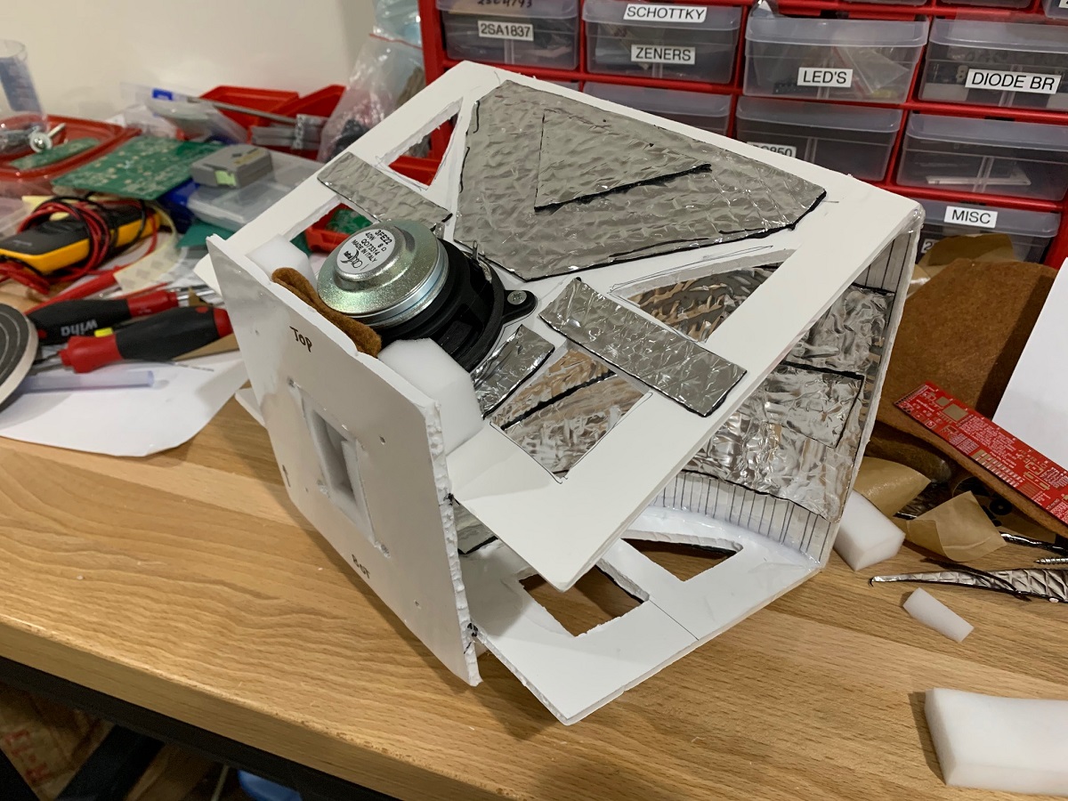
Those dual 3FE22’s get wicked loud - about 105 to 107dB at 2.83v - wear ear plugs when doing sweeps.
M
Looks similar!
Those dual 3FE22’s get wicked loud - about 105 to 107dB at 2.83v - wear ear plugs when doing sweeps.
M
I feel concern about the possible effects of the pressure form the M/C driver on the Heil diphragm.
turk182: If you set the iron to the usual maximum 220 °C, this plastic will not soften enough I am afraid. Actually, the surface is smooth enough, only the bridges look awful. It would work as it is now, the loose threads would need a bit of filler or maybe just paint so that they would not vibrate.
xrk971: Thanks - I tried to get as close to the AMT as possible. Actually, it was the Nano Trynergy thread that pushed me a bit forward to move on with this project🙂
Pharos: The Heil diaphragm looks like it can handle it.
xrk971: Thanks - I tried to get as close to the AMT as possible. Actually, it was the Nano Trynergy thread that pushed me a bit forward to move on with this project🙂
Pharos: The Heil diaphragm looks like it can handle it.
I never had any issues with pressure - the diaphragm is a pleated structure and would simply “accordion out” to handle the pressure. I don’t think it would be damaged easily.
- Home
- Loudspeakers
- Multi-Way
- ESS AMT-1 in my projects