Shouldn't it be pretty straightforward to identify bits that ring by striking them or singing to them (like long welding-rod stators and sheets of perforated aluminum)?
I've found that there are buzzes I can hear when the panel is driven by an audio signal but that I can't hear by simply tapping on it. I'm sure there are some types of noises that can be excited through either mechanism, but it seems others are excitation specific.
Few
Hi,
I have found some sources of buzz in my panels as well :
1) Corona where copper contacts the coating. It looks like copper must be glued on top of the film and coating applied before and after.
2) Some conductivity of the ESL construction itself. In my case PVA glue was used to bond PVC wires to frames made from plywood. Unfortunately glue seems to be (very)slightly conductive. It extrudes perhaps 0.1 - 0.2 mm closer to the film and allows for more pronounced leakage to occur. It appears as a low level corona hissing sound while driving with low frequency and at high output.
Some questions to wire ESL experts here.
1) I have read multiple posts by Capaciti where he mentioned not to use mechanical tension as this makes decay plots worse. I have tested this with a 2um film and it looks like thermal treating does not improve things, maybe even makes it worse. Maybe 2um is too thin? I have tried to treat the film two times, and the second time seems to be the worst. Also I have discovered that the film has developed more tension in the longitudinal direction.
What should be better : 2um film with mechanical tension or 6um thermal?
2) Capaciti seems to be not here anymore. Anyone knows some guidelines where its better to place silicone dots for better decay? Is it possible that when these dots are anchored well it can transfer the energy to frames and material resonances are excited?
Regards,
Lukas.
Wouldn't be the saddle surface a solution to the fundamental resonance and need for (excessively) tensioning of the diaphragm?
http://www.tensile-structures.de/ts_examples.html
http://www.tensile-structures.de/ts_examples.html
Unfortunately not all polyester film is created equal. Some brands heat shrink uniformly in both directions. Other brands mainly shrink only in one direction. And some brands hardly shrink at all. You can draw a square on a test sample of the film, measure, heat shrink, and re-measure to determine how your film will behave when attached to your ESL frame and heated. The best way I have found to apply uniform heating to the film is the use of a temperature controlled model airplane film shrink iron.What should be better : 2um film with mechanical tension or 6um thermal?
http://www.diyaudio.com/forums/plan...con-dots-resonance-control-2.html#post1944318
Yeah, I miss picking Capaciti’s brain 😉 …although he couldn’t give away all his trade secrets.Capaciti seems to be not here anymore. Anyone knows some guidelines where it’s better to place silicone dots for better decay? Is it possible that when these dots are anchored well it can transfer the energy to frames and material resonances are excited?
I believe Calvin mentioned that Capaciti had given up ESL business and returned to the medical field.
The best placement for dots that I found was along the center line of the odd resonance modes since these are the modes that show up in far field CSD plots.Obviously a line of dots down the middle to tackle the (1,1) mode.
Next a line of dots at 1/6 and 5/6 of the panel width to tackle the (1,3) mode.
I never experimented further as I found the application technique of the silicone dots was critical to avoid buzzing noises from the diaphragm flexing near the dots at high excursions. Also, as you mentioned, the dots transferred considerable vibration into the frames. I changed built configurations to using narrow full length spacers rather than dots. Frames are stiffer and diaphragm motion is clean at low frequencies.
Last edited:
I think that ESL's require far more damping that people have thought. I have thought for some time now that 20-30 % open area of the stators is what is required to properly damp a panel. I was using acoustical resistive damping in the early eighties. Just my two cents worth. Best regards Moray James.
I think that ESL's require far more damping that people have thought. I have thought for some time now that 20-30 % open area of the stators is what is required to properly damp a panel. I was using acoustical resistive damping in the early eighties. Just my two cents worth. Best regards Moray James.
I agree that proper damping of ESL diaphragm modes requires some form of resistive damping. However for many people, having see thru panels is a high priority so another method of damping must be used. If the ESL panel is operated as a hybrid rather than full range, resistive damping is usually not necessary if steep crossover networks and/or notch filter are used.
The amount of resistive damping is dependent not just on the % open area, but also on the size of the openings. So a 30% open area wire stator built with #32 wire would provide more resistive damping than a 30% open area wire stator built with #16 wire.
I had posted some measurements of resistive damping results for thin felt and silk screen mesh a few years ago.
http://www.diyaudio.com/forums/plan...con-dots-resonance-control-3.html#post1958582
Quad uses the mesh damping. You can use damping to control the radiation pattern as well as to damp the diaphragm> I never built with 32 gage that's very fine but I did build with 28 and 30 gage. With fine gage wire you need to develop a light touch as it is easy to stretch the wire. Best regards Moray James.
Hi,
I am using the film advertised as Mylar C from ebay. I have also tried hostaphan but in my opinion Mylar C(if its really that) is superior in strength and stability.
I have tried rather thick felt around 4mm thick. Applied it directly on top of the wires(~3.5 mm from diaphragm). Subjectively difficult to judge, but in my opinion the overall sound quality was better with it. Also there was a modest improvement in CSD plots and slight drop in midrange SPL.
Interesting is the impression that the speaker is easier to localize with felt damping. I have a hypothesis that it might have something to do with reduced rear radiation , so reflections are somewhat reduced too and brains interpret it different.. Don't know how to test that.
Did acoustat use damping material only on high frequency segment? It was felt too?
Regards,
Lukas.
The pads which Acoustat used were only to provide additional resistive load as the diaphragms were not tight enough for their width to be 100% dynamically stable. In other words if you played them really loud with high levels of bass with out the felt they would collapse and after enough time even with the pads you could make them collapse. Since the diaphragms were heat shrunk to tension (Mylar HS65) you could only get them so tight. Hope this helps. Best regards Moray James.
The pads which Acoustat used were only to provide additional resistive load as the diaphragms were not tight enough for their width to be 100% dynamically stable. In other words if you played them really loud with high levels of bass with out the felt they would collapse and after enough time even with the pads you could make them collapse. Since the diaphragms were heat shrunk to tension (Mylar HS65) you could only get them so tight. Hope this helps. Best regards Moray James.
Hi,
I have also observed that with heat shrinking the tension is lower, and the film tends to collapse without damping. Also it looks like that the tension obtained with a heat gun is not very uniform; I can't understand how acoustat could use this... Perhaps a controlled temperature small iron would be better, like modeling iron used by Bolser.
Also I am in a long and difficult way to finding sources of hiss and buzzing noises while doing a sine sweeps. It looks a bit a mystery to me as there seems to be no apparent reason for this.
I am using slow curing epoxy for bonding mylar to the spacers. Initially the glue does not form a strong bond but over time the adhesion improves a lot. From the picture of quads it looks like the corners of spacers are not 90 degress but rounded? Is it possible that 90 degree horizontal and vertical spacer connection can contribute to noises ?
Regards,
Lukas.
Lukas: I shrank a lot of Mylar HS 65 and 150 gage film and had no problem achieving uniform tension using a heat gun. Hair dryers won't do the job well as they do not generate enough heat. The real problem with HS is that you are going to loose some of your stretch over time playing. The solution is to switch to a C grade Mylar and stretch your skins.
It is amazing how much sound almost invisible bits of debris can make you will find them at the point where the diaphragm meets the frame. That is most likely your problem not the spacers. Good luck with that. Best regards Moray James.
It is amazing how much sound almost invisible bits of debris can make you will find them at the point where the diaphragm meets the frame. That is most likely your problem not the spacers. Good luck with that. Best regards Moray James.
Lukas: I shrank a lot of Mylar HS 65 and 150 gage film and had no problem achieving uniform tension using a heat gun. Hair dryers won't do the job well as they do not generate enough heat. The real problem with HS is that you are going to loose some of your stretch over time playing. The solution is to switch to a C grade Mylar and stretch your skins.
It is amazing how much sound almost invisible bits of debris can make you will find them at the point where the diaphragm meets the frame. That is most likely your problem not the spacers. Good luck with that. Best regards Moray James.
Thanks, I was already losing hope to fix buzzing noises. Gonna try to be much more careful with removal of the dust this time; hope the things improve.
I have tried to use the heat gun two times recently. At first time I used 2um film. It was stretched on the table to 2% elongation, mostly across the width. Then glued to the speaker. After some time it was heated with a heat gun by using slow motion from controlled height. I guess the temp. should have been around 200C or so. It lost almost all the tension, thats understandable. But then I heated it from longer distance(~14cm) with fast moving motion several times , to perhaps ~160C. I have used temp. meter to measure this. It has regained the tension again! Thats a mystery to me.
Another time I have experimented with 6 um mylar. First I stretched it a bit, then heated several times to perhaps ~160C, then stretched a bit again, and heated again. It was then glued to the panel. This time most of panel has had relatively low tension but one part has had more.
So my conclusion is that perhaps mylar tension is quite sensitive to temperature and duration of heating, or maybe you have other ideas?
By the way, with just mechanical tension I always get quite predictable results. Just concerned about partial resonances of mylar mentioned by Capaciti in several places caused by that.
Regards,
Lukas.
Last edited:
Ok,
So lets go back to the original topic.
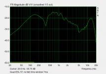
Recently I have measured Quad 57 original speaker(not rebuilt, but not too bad) in three configurations:
1) No damping felt, no front grille
2) Damping behind treble unit, no front grille
3) Damping felt & back grille with its own damping pads, no front grille
Some quite important conclusions can be made :
a) There is a large peak in frequency response without damping felt peaked at ~650 Hz. This can be attributed to resonance of treble unit. Where from is the idea floating around that its resonance is supersonic ?!
b) Added damping on the back significantly influences frequency response of this speaker, making it a lot more linear.
So lets go back to the original topic.
Recently I have measured Quad 57 original speaker(not rebuilt, but not too bad) in three configurations:
1) No damping felt, no front grille
2) Damping behind treble unit, no front grille
3) Damping felt & back grille with its own damping pads, no front grille
Some quite important conclusions can be made :
a) There is a large peak in frequency response without damping felt peaked at ~650 Hz. This can be attributed to resonance of treble unit. Where from is the idea floating around that its resonance is supersonic ?!
b) Added damping on the back significantly influences frequency response of this speaker, making it a lot more linear.
Attachments

Last edited:
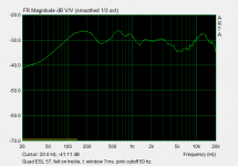
The HF peak is at 15 kHz, it is determined by the diaphragm thickness. But what is the dip at 350 Hz? Some phase cancellation of the bass and treble panels at the measuring distance?
I measured mines at 3m, using a pink noise generator and an Leq meter with 1/3 octave filter. It gives more realistic curve (closer to what you hear when listening to music).
I measured mines at 3m, using a pink noise generator and an Leq meter with 1/3 octave filter. It gives more realistic curve (closer to what you hear when listening to music).
The peak at 15Khz is most likely caused by the resonance of the tranrformer from its leakage inductance and the total capacitance of the panel and the transformer self capacitance.
Its common that this resonance can occur in this range and is normally damped by using series resistor in the primary side of the transformer.
To test this you can add a small bit of capacitance to the panel by paralleling it to the panel and see if this peak shifts down in frequency.
Just make that your added capacitor can handle the voltage.
A piece spare piece of double sided PCB may work nicely for this test.
As for the dip at 350Hz this could be caused by room reflections.
Check for any distances that correspond to a wavelengths of this frequency.
I get a similar dip at around 250hz at a spot in my room (in the corner above the cabinets) and I determined that it was caused by the distance from the top of cabinet to the ceiling as it is approximately 4.5' to 5.5' or so.
jer 🙂
Last edited:
Hi,
I have used windowed measurements at 7ms and mic distance of ~1m.
Bass frequency response should be taken with a grain of salt, as room will have some influence despite it's a dipole speaker.
My interpretation of the dip at 350 that its just because the frequency is right between two resonances : bass panel centered at ~95Hz and mid/treble panel at ~620 Hz. My DIY speaker does not show similar effects but its much taller(and narrower) than quads.
The rise of treble could be attributed to both transformer resonance and maybe even more important increasing beaming of the treble unit which has a center strip about 50mm wide.
Regards,
Lukas.
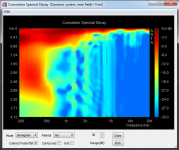
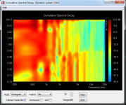
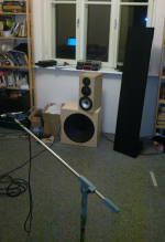
Dynamic vs cone sonograms
Hi,
Today I have run some experiments comparing dynamic system to an esl.
My main question is how do these behave in a typical living room. Mine is 3.6x3x2.8(h)m.
Systems under comparison :
ESL is a DIY segmented element having radiating area of 24x145cm.
Dynamic system: AL170(visaton)+Dayton RS-52AN(dayton)+KE25SC(visaton), box sealed and stuffed with fiberglass.
In both cases active crossovers were used implemented via miniDSP.
The run :
1) ESL element at compromised position(close to the wall , but at an angle), near field
2) ESL element at compromised position(close to the wall , but at an angle), at about 1.6m
3) ESL element at good position(far from back wall), around 1.6m
4) Dynamic system next to the ESL, near field
5) Dynamic system next to the ESL, 1.6m
Plots were calculated using FFT length=256 samples, 100FFT blocks max.
So, my conclusions :
a) ESL element shows more reflections at higher frequencies if placed close to a wall.
b) ESL system has degraded performance between near and far field measurement
c) Dynamic system shows very degraded performance in far field compared to near field , f < ~2kHz.
So maybe it's the dipole action and large radiating area is what makes ELS so special ? 🙂.
Any one has performed similar tests or maybe has an interest to do so?
Lukas.
Attachments

i agree felt is needed to damp. i really cant measure difference in output at higher frequencys, and it sounds tighterand it will pull down resonance by more then 12 dB. i think its worth it, so much for see trough in my opninion
Hi,
Today I have run some experiments comparing dynamic system to an esl.
My main question is how do these behave in a typical living room. Mine is 3.6x3x2.8(h)m.
Systems under comparison :
ESL is a DIY segmented element having radiating area of 24x145cm.
Dynamic system: AL170(visaton)+Dayton RS-52AN(dayton)+KE25SC(visaton), box sealed and stuffed with fiberglass.
In both cases active crossovers were used implemented via miniDSP.
The run :
1) ESL element at compromised position(close to the wall , but at an angle), near field
2) ESL element at compromised position(close to the wall , but at an angle), at about 1.6m
3) ESL element at good position(far from back wall), around 1.6m
4) Dynamic system next to the ESL, near field
5) Dynamic system next to the ESL, 1.6m
Plots were calculated using FFT length=256 samples, 100FFT blocks max.
So, my conclusions :
a) ESL element shows more reflections at higher frequencies if placed close to a wall.
b) ESL system has degraded performance between near and far field measurement
c) Dynamic system shows very degraded performance in far field compared to near field , f < ~2kHz.
So maybe it's the dipole action and large radiating area is what makes ELS so special ? 🙂.
Any one has performed similar tests or maybe has an interest to do so?
Lukas.
wel as the esl is more of a line array dispersion vertical is limited of the esl so less room reflections. far field, then the dynamic version
I recently bought thick household polyester foil for dynamic speaker experiments. I didn't start the experiment because it was ringing so badly. The 6µ foil in ESLs it works more or less because of the damping of the air load. But polyester foil is no longer up to date for high performance applications, anyway. Time to test PEEK foil for ESLs, I find.
Last edited:
- Home
- Loudspeakers
- Planars & Exotics
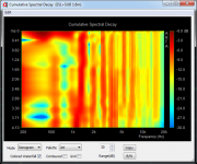
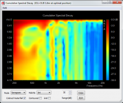
- ESLs have bad decay plots