True, but are there commercial recordings made in native DSD256 or DSD512? ...
I don't know, I just mentioned that AT1201 is one of available ADC chip, which is able to convert directly to DSD256.
Or, are there maybe native DSD256 ADC products used in tracking and or mastering?
ADC will not help, because for most records, signal processing is usually provided in PCM.
True. Yet John Westlake insists that only DSD A/D and DSD D/A is optimal. He says if it is ever converted to PCM then will not sound as good. Personally, I don't have an opinion on that since I have not had the opportunity to A/B compare any differences.
Again, and in reference to Daniel's comment, I don't think there are native DSD256 recordings available. Conversion to DSD256 in software or hardware is always a possibility.
Again, and in reference to Daniel's comment, I don't think there are native DSD256 recordings available. Conversion to DSD256 in software or hardware is always a possibility.
Last edited:
True. Yet John Westlake insists that only DSD A/D and DSD D/A is optimal. He says if it is ever converted to PCM then will not sound as good.
Maybe. But this is possible only for "live records", without any processing and mastering.
DSD lost the format war, has now the dinosaur status, it will disappear as much as the SACD did. DXD or a derivative is the future. John Westlake bets on a dying horse.
If I may interrupt here...........
There are indeed recordings made in DSD256 with Merging's Horus recording system. Channel and Polyhymnia have them and record in DSD256. Channel is a label and Polyhymnia is a recording studio. IF you look at the nativdsd website it lists recordings made in DSD256. There is also a listing for DSD256 files. Some are native recordings and some are from DSD64 recordings. There's not a lot, but they are there.
As for sacd, the sacd line at DADC is still going strong. BIS records in Sweden releases 6 titles each month in sacd and has been doing so for nearly 10 years. There are still numerous small independent Dutch and German labels releasing sacd's as well. Also, sacd is still quite strong in the Japanese market. These discs are mostly all reissues from the Universal Music Group back catalog.
Understand that this is all classical music, irrelevant to most folks and but a spit in the ocean in the overall music industry outside the western European countries.
DSD lost the format war, has now the dinosaur status, it will disappear as much as the SACD did. DXD or a derivative is the future. John Westlake bets on a dying horse.
Since John is in the biz, I am sure he will be flexible and switch horses when it is convenient, as they all do. 🙂
True. Yet John Westlake insists that only DSD A/D and DSD D/A is optimal. He says if it is ever converted to PCM then will not sound as good. Personally, I don't have an opinion on that since I have not had the opportunity to A/B compare any differences.
Again, and in reference to Daniel's comment, I don't think there are native DSD256 recordings available. Conversion to DSD256 in software or hardware is always a possibility.
I remain convinced DSD was really just a front for DRM/copy-protection. Sony loved it because PCs couldn't touch it (DSD/SACD) for a while. When it was developed, copying/ripping CDs was a threat to their business model.
DSD never really made any technical sense when compared with high-res PCM. I'm sure some of these recordings sound lovely, but probably because they are done by people who care about sound quality, and not because they are using DSD converters.
The DSD/PCM thing goes back 20 years, from the beginning.
For sure, one bit makes no sense as a recording format as there is no allowance for post processing. That makes it pretty limiting as a recording format.
The DRM issue was big, for awhile to some labels. However, the Beyonce Knowles copyright lawsuit, that she won, was far bigger in the long term. It essentially ended hybrid sacd discs of new popular music.
The multichannel specifications in the sacd scarlet book initially differentiated sacd. Then a few years later along came blu ray audio, not that that has amounted to very much.
In the end, it just gets to what you like to listen to and what is available for that.
For me at least, there is a factor that some of today's dac chips sound better to me and to people I know when operating in DSD256 mode. Its my preferred way to play CDs. Doesn't matter if its an uncommon distribution format.
Still busy with some experiments with the power supply. Shortly, I will post my experience to power the standard clock by batteries.
A next step may be to look into the I2C control. Just to check on that, for as far as I understand from previous posts: can the standard board V1.07 be used for the adjustment of the I2C settings by assistance of an Arduino? Like this reference from post 7086:
ES9038 Q2M Dac Dsd Decoder Board Ondersteunt Iis Dsd 384Khz Coax Fiber Dop|Home Automation Kits| - AliExpress
Or should the one with the display and encoding switch of post 7088 be used:
ES9038 Q2M DAC DSD decoding board supports IIS DSD 384KHz coaxial fiber DOP|radiator| - AliExpress
knowing that Markw4 in a reply at
https://www.diyaudio.com/forums/digital-line-level/314935-es9038q2m-board-709.html#post6571468
noted that the display or/and switch my not be working after re-programming.
So far as know, there are no DSD256 A/D converters. Some people convert 16/44 PCM CD audio to DSD256 (or higher). Software to do that is made by multiple vendors, with HQ Player probably being the most talked about.
Hardware conversion to DSD is possible as well. There are a few threads in this digital section of the forum which discuss that.
The current de facto system for recording / editing any hi-rez format is Pyramix with various H/W options. There are others but Merging is by far the
most widely used and complete system. They were originally using the Arda ADC's for DSD256 but have moved to AK5578 in the latest modules.
DSD256 is converted to 24/384 PCM if editing is required.
TCD
They were originally using the Arda ADC's for DSD256 but have moved to AK5578 in the latest modules.
ARDA AT1201 is obsolete now 🙁
It was not so good for the measuremets (I tried to use it), but was very good for recording.
... can the standard board V1.07 be used for the adjustment of the I2C settings by assistance of an Arduino?
Yes. There is always a way. Depending on the firmware version in a green board, it can be simple to stop the MCU from accessing I2C bus just by installing some jumpers. Otherwise, there are ways to modify the board to allow temporary or permanent control of the I2C bus by Arduino or some other device. For one example, RPi has been used for I2C control by a few people.
In the very worst case, if modding a dac board to allow Arduino to control the I2C bus, and if the on-board MCU were to accidently become damaged, then Arduino could be used for all dac control. Its not that hard to do.
Besides, getting some experience with I2C bus can open up a lot of new possibilities to work with other chips that use control registers. No need to avoid them just because they need a little programming.
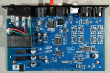
Herewith an update on the power supply of the familiar ES9038q2m board.
The various steps taken over time are:
- an active rectifier for both analog and digital power supplies. This required quite some capacitance – 20.000 uF per supply - to obtain a modest ripple.
- as a second stage some K-multipliers. Not much ripple left after this stage.
- for the analog supply the latest Denoiser with LM317/337 (see threads by Elvee and others)
- the regulators for the digital supplies are 3 x LT1963 (5V / 3.3V)
- the latest experiment is with a separate 3.3V supply for the clock. The standard clock draws a measured 6 mA. At first the idea was to use a low current TLV431 with a set of 4 x NiHM batteries of 1.300 mA/hr. However, the output voltage appeared not to be too stable when the batteries drained in capacity. So the solution for now is a LT3042 set to 3.3V, which draws 2mA by itself. As soon as the mains power is on, the power can be relay switched to regular power. Also, the power connection can be easily connected to the original board supply for the purpose of comparing. See the extra board connector on the picture.
Why this experiment: it takes quite some time for a clock to be audibly stable. At least a few hours, and it even may take a few days. One may leave the dac simply powered on endlessly, of course. But I like to be around when my diy builds are on power (also related to possible insurance risk, one may never know even with very careful building). Usually it takes some 15 to 30 minutes for warmup of the audio set; yes, except for the dac clock. Please no flames here, just my experience. Hence, the batteries. Up to now, the batteries last somewhat over four days. I am hesitant to use a large capacitance battery bank, as most have some sort of switching booster to meet the required voltage.
Any suggestion to reduce the current draw of the battery supply are welcome. For instance: how much voltage would a clock really need to ‘stay on temperature’ when the dac is idle?
Finally for now, is it worth the effort? I did take audition notes of all the various steps. For me, every step was an improvement. Actually, I should go back to the basic initial setting to verify the experience. But hey, the recent separate supply of the clock did so much for a tighter bass, a more natural decay in notes, better separation of instruments/voices, etc that something in me is procrastinating such a basic verification.
Attachments

An update about how to connect a separate output stage as mentioned in post 6946 -6954. The post yielded as an insight of JensH that the four resistors of 6k2 on the dac board would not have to be unsoldered. With the advantage of being able to still listen to the standard rca-output.
As for the separate output stage the following options have passed in this thread:
a. the well described point-to-point output stage of Markw4, as summarize in post 2775, as tight connected to the dac board as possible:
https://www.diyaudio.com/forums/digital-line-level/314935-es9038q2m-board-278.html#post5555503
b. output stage with RPi form factor, a la IanCanada
DocumentDownload/RPiDacHAT/IVboards/IVSTD at master * iancanada/DocumentDownload * GitHub
c. output stage based on the schematic of MrSlim (post 3003), in the version of Green77, aka Daniel (post 5972)
ES9038Q2M Board
and my translated numbering of the bom in post 6946
https://www.diyaudio.com/forums/digital-line-level/314935-es9038q2m-board-695.html#post6517667
The two last versions of an output stage are relatively simple to be build.
For a start, I prepared option b. an output stage of Ian. This is the most simple one to connect right on top of the dac board. The output stage has its own divider for the AVCC, only 3.3V is required.
In first instance, the output stage was equipped with three oldish NEC4557c. The output was somewhat lower than standard, and with a noticeable audible distortion. Next up was a set of LM833 resp. a set of OPA2604. In the last two instances the output was only producing a very low volume, and was heavily distorted. All voltages very ok. Adding 4 x 1nF capacitor to ground on the four dac outputs as per schematic of Ian did not change the result. Also inserting a 4 x 780 ohm in series with the dac output wires did not make a change.
Question: what do I miss?
Not of fan of Ian's output stage design. For one thing both channels share the same AVCC reference since Ian's dac doesn't use separate L/R AVCC regulators. Also, I always found Ian's board to be somewhat distorted sounding. One problem is that its not on the dac board ground plane. I got the best sound out of it by driving it with Ian's dual mono dac board using a ribbon cable folded over in way that seemed to help filter out distortion from RF coming out of the dac analog outputs. I posted a pic of the folded and taped ribbon cable in one of Ian's thread in case anyone else wanted to try it. Attached below for reference.
Attachments

The connection from the dac board to the output stage is about half the length compared to the photo in the previous post.
The serious distortion is really unbearable after already one minute, even with the 4557c's. So it is not just the output design. Strange that the other duals hardly produce any volume. I do have an add-on board with AD797 for to two separate AVCC's, and a subsequent 2 x 1.65V reference voltage.
Is it oscillation somehow? As a next step a scope may reveal what signal is produced.
Or should the 6k2 resistors be removed after all?
What can be a test to check what is going on? As in, for instance: can the output board be tested on its own? If so, what test signal can be fed to emulate the dac output?
If you are shorting AVCC regulator opamp outputs together that might cause some distortion. There is a schematic for Ian's output stage board you can use the check the wiring. I used OPA1612 for all the opamps, although the differential summing stage feedback resistors are pretty low value resistance. IIRC it was designed with OPA1622 in mind for that stage in order to directly drive headphones or something. However, OPA1622 was mounted on a dip-8 adapter which does not correctly ground one of its pins that is supposed to go to ground. IME not properly grounding that increases OPA1622 distortion. One thing to try might be using the differential outputs with some additional stages of passive filtering made with good film caps and metal film resistors. For each channel there would be one differential RC filter, and one RC filter to ground for each output signal. In other words, try what AKM did on AK4499 eval board for differential (XLR) output filtering. Its not a greatly effective filter, but it doesn't sound like too many opamps in a row either.
Another thing that might help would be powering the output stage opamps as I described in earlier posts using a R-core transformer with separate windings, etc. Also, it might help to bypass opamp power rails with film caps instead of X7R ceramics. One more thing that might help would be trying running the opamp rails at a lower voltage, say, maybe +-11v rather than at +-15v.
Another thing that might help would be powering the output stage opamps as I described in earlier posts using a R-core transformer with separate windings, etc. Also, it might help to bypass opamp power rails with film caps instead of X7R ceramics. One more thing that might help would be trying running the opamp rails at a lower voltage, say, maybe +-11v rather than at +-15v.
Last edited:
Hello folks;
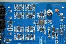
Please see attached layout they achieve great results with smps.
They use TPS7A49 + OPA1612 OPAMP Buffer to power up vref_r and vref_l.
What is strange as far as i saw they use only positive power supply for the opamps.
what sorcery is this?
What i also noticed;
They use sctoty diode in every linear regulator input.
They power up audio clock seperate power source.
They use lots of ferrite beads especially in and out of regulators.
They did not use isolation ic for i2s and i2c only seperate ground planes.
What i do not understand;
The function of use lots of STO-23+ 10k resistors components.
What is 16 pin qfn ic just before for each outputs (3 pcs marking:3710 / 2007U)
Why they use resistor and capacitors in the feedback for vref buffer opamp
Attachments
Last edited:
The output opamps will need +- power or else there would have to be DC blocking caps on the output. Other opamps that are never expected to need their outputs to go below ground could be powered from a single positive rail and ground, say, the AVCC buffer opamps. The AVCC opamps may include filtering on the signal to help reduce noise going to the dac chip. The tiny chips by the output connectors are for muting the outputs. Diodes at the inputs of voltage regulators could be for reverse voltage protection; depends how they are connected.
- Home
- Source & Line
- Digital Line Level
- ES9038Q2M Board