Thanks for tips..
I will try to find one at eBay that ships from Europe.
Whould this one work also?
ADUM1201 ADUM1201ARZ Magnetic Isolator Steady Replace Optokoppler BE | eBay
BR // Daniel
I will try to find one at eBay that ships from Europe.
Whould this one work also?
ADUM1201 ADUM1201ARZ Magnetic Isolator Steady Replace Optokoppler BE | eBay
BR // Daniel
Would this one work also?
No. Unless you find one that says its for I2C somewhere in the text, it would be unlikely to work.
Daniel,
The Amtel MCU absolutely does need the pullup resistors in order for I2C bus to work. The resistors are part of the bus and the bus will not work without them.
Also, it doesn't sense to ask if the MCU is always high. The MCU has many pins on the outside and many other parts inside. Each little thing can be at logic-high state or logic-low state at any instant in time. The state of each little part may or may not change millions of times per second.
In addition, devices like Amtel MCUs may be designed so that the function of some of its pins is programmable. The pin may be an analog input, a digital input, a digital output, have an internal pullup resistor or not, etc. Depends on how it is programmed. When a pin of the MCU is to be used for I2C bus, then that pin will be programmed to act as an input and as an (open-drain) output. If you want to understand more than what I can type in a few sentences, then you have some reading to do on your own. After you read some, then you may have more questions. If so, fine to ask them here. To get you started, you might check out: The I2C Bus: Hardware Implementation Details - Technical Articles
...And or: How I2C Hardware Works - I2C Bus
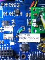
EDIT: In the picture you posted you did not follow the I2C lines from the dac chip correctly. One of the traces you labeled goes down through a via and does not go to the dac chip. Also, I2C pullup resistors could be 10k, although 4.7k might be a more commonly used value.
If you cut the traces going to the dac, the there need to be pullup resistors on side of the bus that goes to the dac chip. If the MCU sees that there are no pullup resistors connected to it, it will probably assume the I2C bus is temporarily busy and just wait for it to come back.
EDIT 2: Looking at your pic more closely, it looks like you did not find pullup resistors on the I2C bus. Remember above when I said the MCU pins can be programmed to have internal pullup resistors turned on? Well, that may be exactly what the dac designer decided to do in this case. If so, and you cut the traces, then the MCU will think I2C bus is not busy and it may think the dac chip is hung and try to reinitialize it or something. If you short the bus pins to ground in that case then the MCU might think the bus is busy.
I made an edit to your pic which I will attach. I marked the trace which you mislabeled. Also, I put little red X marks where I might cut the traces so there is a bit of room to work.
The Amtel MCU absolutely does need the pullup resistors in order for I2C bus to work. The resistors are part of the bus and the bus will not work without them.
Also, it doesn't sense to ask if the MCU is always high. The MCU has many pins on the outside and many other parts inside. Each little thing can be at logic-high state or logic-low state at any instant in time. The state of each little part may or may not change millions of times per second.
In addition, devices like Amtel MCUs may be designed so that the function of some of its pins is programmable. The pin may be an analog input, a digital input, a digital output, have an internal pullup resistor or not, etc. Depends on how it is programmed. When a pin of the MCU is to be used for I2C bus, then that pin will be programmed to act as an input and as an (open-drain) output. If you want to understand more than what I can type in a few sentences, then you have some reading to do on your own. After you read some, then you may have more questions. If so, fine to ask them here. To get you started, you might check out: The I2C Bus: Hardware Implementation Details - Technical Articles
...And or: How I2C Hardware Works - I2C Bus
EDIT: In the picture you posted you did not follow the I2C lines from the dac chip correctly. One of the traces you labeled goes down through a via and does not go to the dac chip. Also, I2C pullup resistors could be 10k, although 4.7k might be a more commonly used value.
If you cut the traces going to the dac, the there need to be pullup resistors on side of the bus that goes to the dac chip. If the MCU sees that there are no pullup resistors connected to it, it will probably assume the I2C bus is temporarily busy and just wait for it to come back.
EDIT 2: Looking at your pic more closely, it looks like you did not find pullup resistors on the I2C bus. Remember above when I said the MCU pins can be programmed to have internal pullup resistors turned on? Well, that may be exactly what the dac designer decided to do in this case. If so, and you cut the traces, then the MCU will think I2C bus is not busy and it may think the dac chip is hung and try to reinitialize it or something. If you short the bus pins to ground in that case then the MCU might think the bus is busy.
I made an edit to your pic which I will attach. I marked the trace which you mislabeled. Also, I put little red X marks where I might cut the traces so there is a bit of room to work.
Attachments

Last edited:
Thanks Mark,
I see my misstake now. I will cut the to traces that are to dac chip.
Not the one going to a via point.
I will connect pullups resistors to the point where i also connect cables. 4.7k to 3.3v.
I order a Adafruit 4 Channel I2C Bi-Directional Logic Level Converter for Arduino Raspberry
as sugested by rfbrw in post #6000.
One more thing, yet again: The isolator would not go where you labeled. If you look at the relay and isolator diagram I recently posted, it shows the isolator near the Arduino, on the other side of the relay from the stuff shown in your pic.
Pullup resistors could be attached at the relay or wherever convenient. They don't have to be right next to the dac chip. The do need to get 3.3v from the dac board however.
Pullup resistors could be attached at the relay or wherever convenient. They don't have to be right next to the dac chip. The do need to get 3.3v from the dac board however.
Deenoo,
Please see attached diagram.
Oops! Just noticed that the signals going back to the MCU are mislabeled in the diagram I posted. SCL-MCU and SDA-MCU should be swapped.
Daniel,
Looking at your pic one more time, it kind of looks like that trace from the MCU that you mislabeled might actually go the reset pin on the dac chip. If so, the MCU can reset the dac chip at any time.
If the MCU loses communication with the dac chip, there is a possibility it will try to reset the dac. That could be a problem for what you are trying to do, so you might want to be prepared to check for that in case it does happen. However, it never was a problem with the MCUs on the older version dac boards. Depends how the new MCU is programmed.
Thanks for all help.
I guess i wait for parts to arrive before cutting anything.
Some parts comes next week.
BR// Daniel
I guess i wait for parts to arrive before cutting anything.
Some parts comes next week.
BR// Daniel
Hi Mark,Deenoo,
Please see attached diagram.
Thank you for the diagram!
Are the schottky diodes (protecting the I2C inputs) connected to 3.3v with cathodes?
Do you drive the DPDT relay with a transistor (pls. type & basis R value?) from USB +5V?
Thanks advance! Dee
Hi Deenoo,
I think I probably used maybe 2n3904 with maybe 4.7k base resistor and with the collector pulling down one end of the relay to near ground. The other end of the relay coil was attached to +5v, and a flyback diode was added across the coil. The coil current was small enough that the transistor could handle it, and small diode was sufficient for flyback use. An Arduino output drove the transistor base through the resistor. Reason for the transistor was because the coil current was a bit more than an Arduino output could drive directly.
Regarding the SR100-TP Schottky clamp diodes, yes, the cathode goes to +3.3v (or +5v) for the chip inputs being protected. Those diodes shouldn't be needed if using an isolator. They were something I used with an 'Arduino Trinket Pro 3.3v' which like the name says it runs on 3.3v instead of 5v like most Arduinos do. No isolator was used in that case. Adafruit Pro Trinket - 3V 12MHz ID: 2010 - $9.95 : Adafruit Industries, Unique & fun DIY electronics and kits
Last edited:
Thank you Mark!
The ADUM1250 will arrive next week.
Does the Arduino work on its own, or do I always need to connect it to my computer via USB? Maybe the program stored inside and use Arduino from a 5V power supply?
THX, Dee
The ADUM1250 will arrive next week.
Does the Arduino work on its own, or do I always need to connect it to my computer via USB? Maybe the program stored inside and use Arduino from a 5V power supply?
THX, Dee
Dee,
First, you're very welcome of course!
Regarding Arduino, it can operate standalone without a computer. Just needs power and it will boot up and run the program in it. So, it depends on if you want to program it to start up and control the dac all the time or whatever.
I think once people see how how to read and write registers from a program, and once they understand better what the registers can make the dac do, then its only a question of how much time and effort they want to put into programming. If they find it fun, then it can be just another aspect of an electronics hobby. If they want a full user interface but don't want to write that much code, then, for example, it may be possible to adapt some or much of Dimdim's ESS dac project code which is available on his website.
After rewriting the suggested registers, do I still need to use Arduino or continue to use the onboard MCU?
The registers will stay as you set them until the dac power is turned off, or until the MCU (or the Arduino) changes them.
With the old MCU firmware on my dac boards, DPLL bandwidth and harmonic distortion compensation register settings were not changed by the MCU when control was returned to it. Doesn't mean the currently shipping firmware is the same.
With the old MCU firmware on my dac boards, DPLL bandwidth and harmonic distortion compensation register settings were not changed by the MCU when control was returned to it. Doesn't mean the currently shipping firmware is the same.
Last edited:
Hi!
My Arduino Due has arravied.
My isolator has not arravied yet so no try.
I quess, if i understod you right Mark, that your code need some parameters to work?
I see that it’s connected to com3 with 9600bits.
BR// Daniel
My Arduino Due has arravied.
My isolator has not arravied yet so no try.
I quess, if i understod you right Mark, that your code need some parameters to work?
I see that it’s connected to com3 with 9600bits.
BR// Daniel
Hi Daniel,
Yes, a few modifications will be needed. First of all though, did you install the Arduino compiler, download and install the I2C library from: GitHub - felias-fogg/SoftI2CMaster: Software I2C Arduino library ...And did you download the pinout diagram for the model of Arduino you have? If you have done all that, then the lines in the program you would have to change are explained in posts #5983, #5987, and #5988. Any questions about those posts, or about any of the other steps? If so, let's just go through them one by one.
Yes, a few modifications will be needed. First of all though, did you install the Arduino compiler, download and install the I2C library from: GitHub - felias-fogg/SoftI2CMaster: Software I2C Arduino library ...And did you download the pinout diagram for the model of Arduino you have? If you have done all that, then the lines in the program you would have to change are explained in posts #5983, #5987, and #5988. Any questions about those posts, or about any of the other steps? If so, let's just go through them one by one.
Forgot to mention, post #5981 suggests to install the Arduino compiler in portable mode. Not necessary to do it that way though.
Hello Mark,
Yes i guess i done all that right. I have a library called SoftI2CMaster and i have installed it in portable mode.
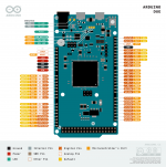
I attached a picture of my Arduino.
In the bottom to the right i have to pins called SDA (D20 and PB12) and SCL (D21 and PB13). Is that something i should use?
BR// Daniel
Yes i guess i done all that right. I have a library called SoftI2CMaster and i have installed it in portable mode.
I attached a picture of my Arduino.
In the bottom to the right i have to pins called SDA (D20 and PB12) and SCL (D21 and PB13). Is that something i should use?
BR// Daniel
Attachments
Hi Daniel.
Looks like you have two sets of I2C pins, the other set being at PA17, PA18 (aka Port A pin17 and Port A pin 18, expressed in the form needed by the I2C library). We will have to read some more about your Arduino to see if one I2C set of pins should be preferred over the other.
...a bit later: Okay, some info about Arduino DUE I2C pins at: Arduino - Wire
Also, general info about the board is available at: Arduino Due | Arduino Official Store ...by clicking on the 'Documentation' tab.
A note about I2C libraries: The default I2C library for Arduino is called Wire. I used the alternate library called SoftI2CMaster because it has some features not available in the Wire library.
After reading at the above links, it looks like you could try using either set of I2C pins just so long as you edit the Arduino program to set the correct port and pin designators for the I2C pins you choose to use. They will probably need external pullup resistors, although if the line in the program that reads:
#define I2C_PULLUP 0
Is changed to read:
#define I2C_PULLUP 1
It will enable the built-in Arduino internal pullup resistors on the I2C pins. Main problem with using those is they are pretty high resistance maybe 50k which may not be enough to be able to run I2C bus at very fast speeds. (The pullup resistors form an RC network with any capacitance associated with the I2C bus and any devices connected to it. A big resistor may only be able to charge up the capacitance rather slowly which would limit how fast the bus could run.)
Last edited:
- Home
- Source & Line
- Digital Line Level
- ES9038Q2M Board