Daniel,
If you have not already loaded the Arduino compiler program, I would suggest to install it on your computer in portable mode: How to create and use a portable version of the Arduino Software (IDE) | Arduino
If you have not already loaded the Arduino compiler program, I would suggest to install it on your computer in portable mode: How to create and use a portable version of the Arduino Software (IDE) | Arduino
I did a download and install in portable mode. So far so good...
But i did take a fast look and understod nothing.. i just remember that my skill in anything doing with programs ends with 3 lines in basic..
BR // Daniel
But i did take a fast look and understod nothing.. i just remember that my skill in anything doing with programs ends with 3 lines in basic..
BR // Daniel
The program will need to be modified a bit to work with your particular Arduino model. The .md file that goes with the github library download is an explanation of the settings to make for a particular Arduino. It also explains the syntax for talking over I2C bus. I can also help with that when the time comes.
Once modified and loaded on your Arduino, there is a serial monitor built into the Arduino compiler that can used to type in commands on your PC while the Arduino is connected to your dac I2C bus. Conceptually, the program allows someone to select a register to read or write, then read and or write to that register as much as you want until you select another default register to communicate with. That was a bit tiresome in cases, so I also added an option to the menu to interactively select a register and read/write to it all from one menu item. (The menu appears in the serial monitor window on your PC, its like an old dumb terminal type of interface.) There are also some special menu options for reading and writing registers wider than 8-bits (which is the standard word length for I2C communications).
I can explain more as you go along. No worries.
Thank you Mark,
I will have the Arudino at the end of the week i guess.
One more thing, i can use mu old green PCB to practies i guess. I will read a bit more in the links you gave me. But i read something about a pullup resistor. Is that something that need to be solder on the PCB?
BR // Daniel
I will have the Arudino at the end of the week i guess.
One more thing, i can use mu old green PCB to practies i guess. I will read a bit more in the links you gave me. But i read something about a pullup resistor. Is that something that need to be solder on the PCB?
BR // Daniel
I2C control bus is an 'open collector' or 'open drain' type bus. In order for many devices to use the bus without creating a short circuit, none of the connected devices uses active pull up to assert a logic high state. Instead a pair of pullup resistors pull the bus up to 3.3v (in this case at least) and connected devices can only pull the bus down towards ground to assert a logic low state.
One of the links in the list I pointed to has a pic of a dac board with two resistors shown. One end of each resistor is circled in red. Those are the I2C pullup resistors and the circled end is the I2C bus side of the resistors. One resistor for SCL, and the other is for SDA.
The point in that pic was that one can solder leads to the I2C bus at that point for one set of I2C connections going to the Arduino. Where else the Arduino's I2C seizure relay would need to be connected would depend on where the I2C bus has been disconnected from the MCU. You may recall that I used two different methods to disconnect the MCU from the dac chip and connect the Arduino instead. One method involved lifting two MCU pins, the other method involved cutting I2C traces going between the dac chip and the MCU, and soldering small leads on to the cut traces.
Last edited:
#Mark4Which model of Arduino do you have?
If you tell me maybe I can better explain what you would need to do.
Arduino Nano Atmega328P-AU 3.0 CH340
will be good?
Thx! Dee
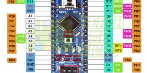
So far as I know, any Arduino should be able to work. Just google the pinout diagram for the model of Arduino you have. For example the pinout for Arduino Nano is attached below.
Looks for the pins labeled SCL and SDA. Those or the I2C bus pins for that model of Arduino. Google found some more info about using Nano (and others) for I2C: Can’t Get I2C to Work on an Arduino Nano? (Pinout Diagrams) | Big Dan the Blogging Man
In addition, I would suggest use of an I2C isolator between the Arduino and the dac chip. Google can find lot of of them, for one example: ADUM1250 Datasheet and Product Info | Analog Devices
Also, a little DPDT relay to switch out the MCU and connect the Arduino: mini DPDT 5v relay - Google Search
If interested, there are some pics of my Arduino setup attached to post #1412 of this thread. It shows another little red board attached to the 'Arduino Trinket Pro 3.3v' model that I use. That red board is an FTDI to USB interface which is needed with Trinket for real time USB communications while a program is executing. Most Arduinos don't need that extra board, but Trinket is an exception. Don't know about Nano, but it could be similar in that regard.
Attachments
Last edited:
One more thing since we are talking about Arduinos and the software I used with it for dac register access. The .md file for the I2C library says (in part):
"In the program text before the include statement, some compile-time parameters have to be specified, such as which pins are used for the data (SDA) and clock (SCL) lines. These pins have to be specified in a way so that port manipulation commands can be used. Instead of specifying the number of the digital pin (0-19), the port (PORTB, PORTC, PORTD) and the port pin has to be specified. The mapping is explained here. For example, if you want to use digital pin 2 for SCL and digital pin 14 (= analog pin 0) for SDA, you have to specify port pin 2 of PORTD for SCL and port pin 0 of PORTC for SDA:
#define SCL_PIN 2
#define SCL_PORT PORTD
#define SDA_PIN 0
#define SDA_PORT PORTC
#include <SoftI2CMaster.h>"
The above text includes a link to the information at: Arduino - PortManipulation
Generally speaking, the pinout diagrams for different model Arduinos show all the required pin and port information to customize the program for your particular Arduino.
The only other information in the program that may have to edited is the baud rate to use for talking to the Arduino compiler program's Serial Monitor. Since I use an FTDI board for that communication the baud rate for me is limited to 1200 baud. The line in the program that specifies the baud rate to use is:
Serial.begin(1200);
EDIT: Some additional information about starting up the dac cold without the MCU is discussed in a few posts starting around #5607
Last edited:
Mark, what (SDA+SCL or Vcc/Vdd) do you switch with the mini DPDT relay, and how many contacts(1 or 2 morse) it have?So far as I know, any Arduino should be able to work. Just google the pinout diagram for the model of Arduino you have. For example the pinout for Arduino Nano is attached below.
Looks for the pins labeled SCL and SDA. Those or the I2C bus pins for that model of Arduino. Google found some more info about using Nano (and others) for I2C: Can’t Get I2C to Work on an Arduino Nano? (Pinout Diagrams) | Big Dan the Blogging Man
In addition, I would suggest use of an I2C isolator between the Arduino and the dac chip. Google can find lot of of them, for one example: ADUM1250 Datasheet and Product Info | Analog Devices
Also, a little DPDT relay to switch out the MCU and connect the Arduino: mini DPDT 5v relay - Google Search
If interested, there are some pics of my Arduino setup attached to post #1412 of this thread. It shows another little red board attached to the 'Arduino Trinket Pro 3.3v' model that I use. That red board is an FTDI to USB interface which is needed with Trinket for real time USB communications while a program is executing. Most Arduinos don't need that extra board, but Trinket is an exception. Don't know about Nano, but it could be similar in that regard.
Can you draw a schematic about the application of the ADUM1250 and the relay?
Thank you! Dee
Last edited:
I prepared a short demo about how to use ES9038Q2M/Pro harmonics compensation registers via Android app E1DA TWEAK App THD Demo - YouTube
Hello,
Still looking for parts for the Arudino try.
How importen is the I2C isolator if you power the Arudino from same power as the Dac?
I’m strugeling to find one here in Sweden.. or maybe i’m missing something..
BR // Daniel
Still looking for parts for the Arudino try.
How importen is the I2C isolator if you power the Arudino from same power as the Dac?
I’m strugeling to find one here in Sweden.. or maybe i’m missing something..
BR // Daniel

How importen is the I2C isolator if you power the Arudino from same power as the Dac?
The dac chip runs on 3.3v, however its I2C pins are 5v tolerant when the dac chip is powered on. Also, Arduino pins can be damaged if non-power pins exceed Vdd. In both cases the devices could probably be protected by using Schottky diodes to clamp interface pins so they can't go higher than Vdd (even when Vdd=0v which happens with the device is powered off). However, some Schottky diodes have enough reverse leakage to damage device pins during turn on transients when a device is just powered on. A diode I have found to be safe is: SR100-TP
Any other means you can think of should be fine too. The point is to make sure that neither the dac chip nor the Arduino can be accidently damaged by the other, even during transient conditions. Another possible way to consider might be to disable the relay coil when both devices are not already powered on.
Last edited:
One more thing probably worth explaining is what DPDT means. The letters stand for Double-Pole, Double-Throw. A 'Pole' in this case can be thought of as a common terminal on a multi-position switch or on a relay. A 'Throw' can be thought of as one of the terminals that a common terminal can be switched to.
So, a DPDT relay has two common terminals, and each common terminal can be connected to two different switch-position (or relay-position) dependent terminals.
In the diagram I posted, the common terminals of the relay go to the dac chip's SDA and SCL pins. The position-dependent terminals (N.O. and N.C.) go to the MCU and to the isolator chip. (N.C. stands for 'normally closed' where the 'normal' condition is when the relay is de-energized.)
The terminology 'DPDT' may be more commonly used by electricians, but its something electronics guys should be familiar with too. Other similar terms include SPST, SPDT, DPST. Also, electricians have some things called a 3-way switch and 4-way switch. Google may be helpful for those, they have possibly interesting internal construction.
Last edited:
I did order this one..
Red 2 channel opto-isolator Breakout for optoisolator optocoupler | eBay
BR // Daniel
Red 2 channel opto-isolator Breakout for optoisolator optocoupler | eBay
BR // Daniel
Seems doubtful that particular opto-isolator is going to work for I2C. First of all, optos only couple in one direction. They are probably rather slow devices as well. Do you have some clever way to use them bi-directionally?
Maybe I should explain some more just to be sure we are both on the same page (so to speak): The way I2C bus works in this case is that the bus master generates all the clock signals, with the bus master either being the dac board MCU or the Arduino. On the other hand, any device on the bus can generate SDA signals by pulling down the SDA line. The Arduino will control SDA when sending commands and or data to the dac chip, the the dac chip will control SDA when the Arduino is reading dac chip register contents. It means that at least the SDA isolator has to be bi-directional. That's something all isolators designed for I2C have to be able to do.
Maybe I should explain some more just to be sure we are both on the same page (so to speak): The way I2C bus works in this case is that the bus master generates all the clock signals, with the bus master either being the dac board MCU or the Arduino. On the other hand, any device on the bus can generate SDA signals by pulling down the SDA line. The Arduino will control SDA when sending commands and or data to the dac chip, the the dac chip will control SDA when the Arduino is reading dac chip register contents. It means that at least the SDA isolator has to be bi-directional. That's something all isolators designed for I2C have to be able to do.
Last edited:
Guess maybe I should add another comment which is that if anyone decides to use an isolator chip of any kind, please be sure to read the data sheet to make sure you are using the part correctly. For example, bypass caps may be required, or there may be other issues to consider.
I hear you Mark, make seens now.
Hmm, i was maybe a bit quick i didn’t read the datasheet for this..
I was to happy that i found one that wasn’t so expensive to post..
Crap 🙁
Hmm, i was maybe a bit quick i didn’t read the datasheet for this..
I was to happy that i found one that wasn’t so expensive to post..
Crap 🙁
Dimdim uses the SI8605 between the DAC & micro so must work for him.
Arduino controlled Dual Mono AK4490 DAC (Part 2) | Dimdim's Blog
https://docs.rs-online.com/a676/0900766b8131cd3f.pdf
SI8605AC-B-IS1R Silicon Labs | Mouser
$3.71 so pretty cheap
Arduino controlled Dual Mono AK4490 DAC (Part 2) | Dimdim's Blog
https://docs.rs-online.com/a676/0900766b8131cd3f.pdf
SI8605AC-B-IS1R Silicon Labs | Mouser
$3.71 so pretty cheap
- Home
- Source & Line
- Digital Line Level
- ES9038Q2M Board