Yes, sorry.
Should have upload orginal file.
I made it with diptrace.
I can upload it tomorrow if i have it at home.
If i have it work i can upload it after the weekend.
I look tomorrow.
BR// Daniel
Should have upload orginal file.
I made it with diptrace.
I can upload it tomorrow if i have it at home.
If i have it work i can upload it after the weekend.
I look tomorrow.
BR// Daniel
Last edited:
Another question, i have asked this before but try again.
I have changed ny dac board with another es9038q2m board.
Old one was a bit messy from soldering.
Anyway, new board have the same problem locking 48khz pcm from
Samsung tv with optical input.
Every other optical inputs work fine that i have try, but its 44.1 kHz.
Anyone have tried optical inputs at 48khz from tv?
BR// Daniel
Attachments
Last edited:
Hmmm...
Given that you are having the same problem with the old board and the new board with respect to decoding optical SPDIF (also known as TOSLINK) from the Samsung TV, it suggests to me that maybe either the dac board is using a poor quality optical receiver module or that the TV configuration menu might not be set for "decrypted stereo" output mode.
If you were to do the I2C mod on the dac board so that you can take over the dac registers, you could see what the dac chip SPDIF receiver thinks the TV is sending. SPDIF format allows for non-audio formats to be sent and or for some embedded non-audio information to be sent along with normal audio. That information should be readable from a SPDIF status register in the dac chip. Its been awhile since I programmed a SPDIF receiver, but there may be some setting in the dac chip's receiver settings that is rejecting the TV audio when it shouldn't be.
In addition, if you did the I2C mod you would also have control of "DPLL Bandwidth" for potentially significantly improved sound quality in all modes.
Thanks Mark,
I did try another optical reciver, no improvment.
Also tried a dir9001, optical in and i2s out. Same lock problem from Samsung tv.
In tv menu it is set to stereo out. Can’t change kHz or anything else.
Is it somewhere in this thread a guide how to access the dac register over i2c?
BR // Daniel
I did try another optical reciver, no improvment.
Also tried a dir9001, optical in and i2s out. Same lock problem from Samsung tv.
In tv menu it is set to stereo out. Can’t change kHz or anything else.
Is it somewhere in this thread a guide how to access the dac register over i2c?
BR // Daniel
Yes, there is some info on accessing I2C registers. However some of the soldering can be small, and to some people intimidating. There are some links on the subject listed in post #3308 of this thread.
Probably also worth mentioning is that in the very worst case if someone accidently damaged the MCU while trying to fiddle with its I2C pins, its quite possible to run the dac with an Arduino as the MCU.
EDIT: Accessing and using the dac I2C registers also requires understanding some things about the I2C registers and how they are normally configured. That has not been discussed in detail in this thread due to ESS restrictions. Beyond that, PM okay if needed.
Last edited:
Hello,
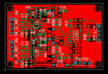
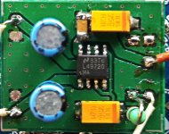
Here is the Gerber file for the PCB i use in my dac.
It's from the schematic in post #3003, except that it doesn't have the unbalanced output.
Works for me but can't say for sure that's a correct PCB. And layout are for sure not optimized.
But a nice improvment over the voltage mode OP that are on the orginal dac pcb...
Reason for R13-R16 is throug hole (i put a SMD 1206 in parallel) is that i couldn't find smd parts.
So if anyone want to build this pcb choose either R13-R16 or R20-R23.
D1 and R19 is also an option, i use it to see that dac was on.
BR // Daniel
Hi
Can you also make unbalanced output please?
Do you also make pcb for avcc circuit from post 3003?
Thx
kimschips,
Daniel said he would upload his source files. There is also a freeware version of the PCB design program he used. Maybe you can start with those things to make your own unbalanced outputs?
Daniel said he would upload his source files. There is also a freeware version of the PCB design program he used. Maybe you can start with those things to make your own unbalanced outputs?
Yes mark I would like that😊
I am still looking for the right Dac board to buy
Not to expensive though.
I am still looking for the right Dac board to buy
Not to expensive though.
Does anyone have success setting the ES9038Q2M in Synchronous mode using the DSD interface, and being the I2S Slave? Is possible ?
Hello,
I did buy a ARDUINO DUE right now.
Is that a good start to access the Dac register?
BR // Daniel
I did buy a ARDUINO DUE right now.
Is that a good start to access the Dac register?
BR // Daniel
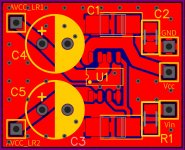
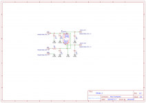
AVCC_LR power supply
(PCB & Schematics, Gerber, Project files)
(PCB & Schematics, Gerber, Project files)
Attachments
-
 AVCC_LR PCB v4.jpg743.1 KB · Views: 361
 -
 Schematic_AVCC-LR_AVCC-LR-Schematic_20190719154610.png164.8 KB · Views: 351
 -
Gerber_AVCC_LR PCB Final_2020-10-15_13-29-26.zip24.1 KB · Views: 104
-
Project_AVCC_LR_20190719124645 v4 project files.zip21.3 KB · Views: 127
-
 IMG_20201019_145345.jpg432.7 KB · Views: 337
Last edited:
I did buy a ARDUINO DUE right now.
Is that a good start to access the Dac register?
Which model of Arduino do you have?
If you tell me maybe I can better explain what you would need to do.
Of course, you have to break into the I2C bus on the dac board first. The links I pointed to earlier show a couple of ways I have done that in the past, either by lifting the dac board MCU I2C pins, or by cutting the I2C PCB traces. I hope that was clear.
Guys,
Thank you for posting Gerbers and source files for output stage and AVCC circuits. I don't have time to take a look at those right now since I am in the middle of something else, but others who know about PCB layout should be invited to take a look.
I would probably be inclined to try to layout the output stage more in the way suggested in the attached diagram (bypass caps not shown but should be included). I think all the components could probably be mounted on the top of PCB if the opamps are oriented correctly with respect to signal flow. If so, then most of the bottom side of the board and a good amount of the top could be used for ground pours so as to make a high quality grounding design for the output stage. That output stage ground should be a continuation of the dac board ground plane to whatever extent possible.
The only thing I might change about the output stage schematic might be to add another pole of passive filtering before the differential summing stage. I think that could probably be done fairly easily.
Attachments

Last edited:
Which model of Arduino do you have?
If you tell me maybe I can better explain what you would need to do.
Of course, you have to break into the I2C bus on the dac board first. The links I pointed to earlier show a couple of ways I have done that in the past, either by lifting the dac board MCU I2C pins, or by cutting the I2C PCB traces. I hope that was clear.
Thanks Mark.
I did order a DUE R3 Board SAM3X8E 32-bit ARM Cortex-M3 Control Module from eBay Germany. It will take a few days to arrive.
I will look more at the links you posted. But just to see if i understand. The MCU is sending registersettings to the dac chip. Is it stored in the mcu, so i need to save new values there? Or in the dac chip?
Sorry for real noob questions, i have never done anything with this type of settings..
BR // Daniel
Daniel,
You would take over control of the I2C bus so that MCU cannot talk to the dac chip. Then you can use the Arduino to talk to the dac chip registers instead of the MCU doing it. You can read and write registers as I will explain in more detail a bit later. The hardware part has to be put together first.
What I did was use a little DPDT 5v-coil relay to switch the I2C bus lines (SCL, SDA) from the MCU I2C pins to the Arduino I2C pins (shown on the Arduino pinout diagram for the model Arduino you have). There is also the matter of protecting the dac chip and the Arduino from each other if they can be powered on/off separately from each other. In that case some kind of "I2C isolator" chip can be used for safety. For example, Sparkfun sells various little boards for that (and their boards have schematics available), or you can make your own solution.
In the meantime, there is a simple program I made for Arduino that can talk to dac registers. It can be downloaded from: Dropbox - Latest.zip - Simplify your life ....Also, it requires a library file that can be downloaded from: GitHub - felias-fogg/SoftI2CMaster: Software I2C Arduino library
Last edited:
- Home
- Source & Line
- Digital Line Level
- ES9038Q2M Board