For some time I have wanted to see how far I upgrade one of the ebay Sabre DAC boards to sound as close to a Benchmark DAC-3 as possible. I'm getting pretty darn close, but I think there is a little more that can be done. More on that later, but for now a couple of photos attached below. As can be seen, output stages are fully balanced IV, power supplies are considerably cleaned up, and a low phase noise oscillator has been fitted.
It looks like You are powering the 1.2 V LDO (which one powers the DVDD) too. Is any reason to do it?
It looks like You are powering the 1.2 V LDO (which one powers the DVDD) too. Is any reason to do it?
Early on, I played around with a different power source for the regulator that came with my board. That was before I went ahead and did the NDA for a data sheet. Later I put the power back that way it was originally for the 1.2v regulator. I guess I could have removed it altogether but I don't think its hurting anything. It just doesn't need to be there.
Wanted to mention that somebody asked me about the Chinese SRC4392 boards that I recommend for the DAC modding project, like this: Free Shipping! 1pc SRC4392 asynchronous Upconversion with USB coaxial optical I2S Decoder board-in Integrated Circuits from Electronic Components & Supplies on Aliexpress.com | Alibaba Group
The question was requesting general information about the board, so I thought it might be of interest to the group if I shared that here for anyone that may be interested. Here you go:
There is no schematic, but it is easy to trace out. Do you have the switch settings, to start with?
There is a jumper on the board J1 by the LEDs. That is to power the board by USB. Otherwise it can be powered from the pin header.
The USB connection goes to a 16-bit DAC on the card, and the DAC has a 16-bit SPDIF output that is one possible input to the SRC. The other inputs are SPDIF and TOSLINK on the end of the board by the USB connector. The pin header has an I2S input. The outputs are SPDIF and TOSLINK at the other end away from the USB connector.
The 16-bit DAC is not good enough for serious use so I would not bother with it. The USB connector can still be used to power the board from a wall wart.
I use the SPDIF input and output. Input comes from a USB to SPDIF adapter or from a computer motherboard, output SPDIF goes to the DAC.
You can read the part numbers on all the chips and download the data sheets with a Google search. The SRC4392 is the main part we are interested in and the data sheet should be carefully studied for full benefit.
There is a small microcontroller chip that scans all the inputs and programs the SRC to work with one of them. I don't know what algorithm it uses to choose if more than one input is receiving audio.
The switch settings I normally use to upsample any input to 192 kHz is
1 = on
2 = on
3 = off
4 = off
Okay, that should be enough to get you started. If you want it should be possible to convert the I2S port to an output instead of an input, but you would have to connect an Arduino to control the SRC4392 chip via I2C bus if you wanted to do that.
What is your main source to play music? The 9038Q2M board is quite good to deal with cd resolution sourced from coaxial input. I am afraid, you introduce more problem with this "crappy looking" board with SRC chip. An usb source could be amanero I2S, or a number of good usb-spdif converters.
Last edited:
I use coaxial input, as you say, only from the SRC board. Also, the board I received looks better than the picture and is red color. You could use an SRC4392EVM board which I have also tried although it costs twice as much as this board, although you might like the looks better it sounds the same as this one. I also use coaxial input to go into the SRC board, from a USB to spdif board. I use a cheap one, but you could use an Amanero if you wanted as they do have a SPDIF output.
Where I have to disagree with you is that the 9038Q2M board is NOT quite good to deal with CD resolution music without upsampling even with an Amanero board, As I have patiently explained many times.
What makes you think any problem is introduced? Looks? Why do you suppose Benchmark DAC-3 and Crane Song Quantum converters use upsampling to 211kHz?
Last edited:
I2C capture
Hi,
I've made some i2C capture on the board
here are my results:
Unfortunately th onboard microcontrolles has fried few days after. I've setup an esp32 with oled display, a rotary encoder + infrared sensor under arduino connected to I2C , it works well I can validate that the I2C commands are sufficent to play pcm content.
regards
Hi,
I've made some i2C capture on the board
here are my results:
Code:
BOOT (write adr, val) :

write 0, 0 // quit reset mode
write 0x1b, 0xd4
write 2, 0x34
write 6, 0x4a
write 0xe, 0x42
write 8   ,0x99
write 0x15, 0x50
write 0x7, 0x40 (set the filter 4 upper bits+ mute mode?)
write 0xb  ,0x30  (set the input)
write 1, 0xc1 (set the input)
write 0xf, 0x0f //volume
write 0x10, 0x0f //volume
read 07 = 0x40  // read to only write bit 0
write 7, 0x40 (unmute ?)

COAX TO I2S:
read 07 = 0x40
write 7 0x41
write 1 0xCC
write 0XB 0x0
read 07 = 0x41
write 7 0x40

I2S --> OPT
read 07 = 0x40
write 7 0x41
write 1 0xC1
write 0XB 0x40
read 07 = 0x41
write 7 0x40

OPT ->COAX
read 07 = 0x40
write 7 0x41
write 1 0xC1
write 0XB 0x30
read 07 = 0x41
write 7 0x40

Signal locked
read 40=0x71 (0x71 for no lock, so bit 0 )regards
The original amanero board outputs I2S only, and I don't have experience with clones (spdif out). For coax I am using a shiga clone as a cd-source (Finally, an affordable CD Transport: the Shigaclone story). And these two (shiga+9038Q2M) for sure are just amazing together without any upsampling.
I have tried upsampling here with multiple SPDIF and TOSLINK sources. Always sound better with upsampling.
Ever wonder why there are a few reconstruction filters in the DAC to choose from? Because they are all audible, and they all have tradeoffs. The one with the least group delay is the minimum phase slow transistion. Unfortunately the transition band exends down into the audio range. But, we can fix that problem the same way Benchmark and Crane Song do, by upsampling. It shifts the reconstruction filter transition band above the audible and audio frequency range. If you play a CD there is no information above 20kHz. We can move the filter transition band up above 20kHz were there is no information, therefore the slow transition if fine, and we gets the benefits of minimal group delay (rate of change of phase of our CD audio with respect to frequency). It sounds better. You can try it or not, but its better. in addition, SRC4392 reduces jitter so now we have two stages of jitter reduction and the DAC has less to do. That's just a bonus in cases where there is jitter.
Anyway, I have tried it different ways and it always sounds better with minimum phase and upsampling. You can try it or not. If you do try it you don't have to use it, or you could use it selectively for CDs but not for for hi-res, up to you. I'm using mine, for sure.
BTW, soon I will begin testing a AK resampler board that I will try using with a plugin XU208 board which comes out with both I2S and SPDIF, which are the outputs I want. I can route it either way and SRC or not with button pushes and a nice display. Don't know how it will sound but decided to find out.
EDIT: Forgot to mention that SRC4392 is rated for -140dB distortion, well below the distortion level of the ES9038Q2M itself.
Last edited:
Unfortunately th onboard microcontrolles has fried few days after. I've setup an esp32 with oled display, a rotary encoder + infrared sensor under arduino connected to I2C , it works well I can validate that the I2C commands are sufficent to play pcm content.
occip, Great to hear from you, and good work! May I ask which Arduino are you using? Also, do you need more code, or is everything working okay? If need be, maybe we can help you.
Mark,
I'm using a TTGO esp32 lora board with the arduino ide (10$) , it has I2S wifi bluetooh and a oled display. My goal is to display signal rate on the screen and maybe control the board through wifi/bluetooth, and maybe to enable the thd compensation.
For the signal rate I Think I can dump all the register to discover the DPLL value for each signal rate ( values read by hifiduino project for 9038Pro.
For thd compensation I've no idea. I've found the Khadas Tone board very promising but no source code for the moment.
My goal is to display signal rate on the screen and maybe control the board through wifi/bluetooth, and maybe to enable the thd compensation.
PM sent.
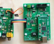
Have some new info to report today. Have been testing the following combination of SRC and USB parts:
sandy AK4137 DAC SRC Audio 384K 32Bit DSD256 DSD IIS Conversion-in Headphone Amplifier from Consumer Electronics on Aliexpress.com | Alibaba Group
New XU208 xmos USB digital audio interface U8 upgrade asynchronous amanero module for hifi amplifier A3 004 003-in Amplifier from Consumer Electronics on Aliexpress.com | Alibaba Group
Distortion rating of this SRC is in the -140dB to -150dB range and yes it sounds a little better than the SRC4392, but only slightly I would say. For someone wanting the very best sound and a nice display and settings options, it could be a good choice.
Connected to DAC board using I2S, 32-bit. At first found I2S with this setup only worked up to 352kHz, so decided to work on that issue.
Added a row of ground pins on the DAC board next to the I2S Data, BCLK, and LRCK pins. Made up a short, maybe 3" double row ribbon cable to connect SRC and DAC. Every other wire is a ground wire, so more of a controlled impedance interconnect now between the two boards. Now works fine with sample rates up to and including 960KHz, which is the highest it could possibly go. Just goes to show respecting RF principles can pay off quite well.
In anyone is interested I could post some pics of how to do the RF interconnect and extra ground pin mods.
Last edited:
Wanted to mention that somebody asked me about the Chinese SRC4392 boards that I recommend for the DAC modding project, like this: Free Shipping! 1pc SRC4392 asynchronous Upconversion with USB coaxial optical I2S Decoder board-in Integrated Circuits from Electronic Components & Supplies on Aliexpress.com | Alibaba Group
The question was requesting general information about the board, so I thought it might be of interest to the group if I shared that here for anyone that may be interested. Here you go:
There is no schematic, but it is easy to trace out. Do you have the switch settings, to start with?
There is a jumper on the board J1 by the LEDs. That is to power the board by USB. Otherwise it can be powered from the pin header.
The USB connection goes to a 16-bit DAC on the card, and the DAC has a 16-bit SPDIF output that is one possible input to the SRC. The other inputs are SPDIF and TOSLINK on the end of the board by the USB connector. The pin header has an I2S input. The outputs are SPDIF and TOSLINK at the other end away from the USB connector.
The 16-bit DAC is not good enough for serious use so I would not bother with it. The USB connector can still be used to power the board from a wall wart.
I use the SPDIF input and output. Input comes from a USB to SPDIF adapter or from a computer motherboard, output SPDIF goes to the DAC.
You can read the part numbers on all the chips and download the data sheets with a Google search. The SRC4392 is the main part we are interested in and the data sheet should be carefully studied for full benefit.
There is a small microcontroller chip that scans all the inputs and programs the SRC to work with one of them. I don't know what algorithm it uses to choose if more than one input is receiving audio.
The switch settings I normally use to upsample any input to 192 kHz is
1 = on
2 = on
3 = off
4 = off
Okay, that should be enough to get you started. If you want it should be possible to convert the I2S port to an output instead of an input, but you would have to connect an Arduino to control the SRC4392 chip via I2C bus if you wanted to do that.
That was me (maybe Someone else too). Meanwhile after your suggestion I ordered the board and waiting exited for the delivery 🙂
Thanks for the additional info.
Sz.
00Reg - working
Hi All,
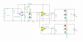
As I announced that I would open a new thread for AVCC power supply. I built the enclosed circuit.(FET is 2SK170BL - not as on the drawing)
The sound is great. See the 66 and 70 posts in the thread:
http://www.diyaudio.com/forums/digi...d-ultra-low-noise-vref-dac-7.html#post5456963
bb.
Just to mentioned I called it 00Reg 🙂.
Hi All,
As I announced that I would open a new thread for AVCC power supply. I built the enclosed circuit.(FET is 2SK170BL - not as on the drawing)
The sound is great. See the 66 and 70 posts in the thread:
http://www.diyaudio.com/forums/digi...d-ultra-low-noise-vref-dac-7.html#post5456963
bb.
Just to mentioned I called it 00Reg 🙂.
Attachments
PS.: although in the mentioned thread you can read some hard sentences between Mark and me, but I have to admit, that finally his idea with the Rout=0 was applied. So thanks Mark for the challanges 🙂
Have some new info to report today. Have been testing the following combination of SRC and USB parts:
sandy AK4137 DAC SRC Audio 384K 32Bit DSD256 DSD IIS Conversion-in Headphone Amplifier from Consumer Electronics on Aliexpress.com | Alibaba Group
New XU208 xmos USB digital audio interface U8 upgrade asynchronous amanero module for hifi amplifier A3 004 003-in Amplifier from Consumer Electronics on Aliexpress.com | Alibaba Group
Distortion rating of this SRC is in the -140dB to -150dB range and yes it sounds a little better than the SRC4392, but only slightly I would say. For someone wanting the very best sound and a nice display and settings options, it could be a good choice.
Connected to DAC board using I2S, 32-bit. At first found I2S with this setup only worked up to 352kHz, so decided to work on that issue.
Added a row of ground pins on the DAC board next to the I2S Data, BCLK, and LRCK pins. Made up a short, maybe 3" double row ribbon cable to connect SRC and DAC. Every other wire is a ground wire, so more of a controlled impedance interconnect now between the two boards. Now works fine with sample rates up to and including 960KHz, which is the highest it could possibly go. Just goes to show respecting RF principles can pay off quite well.
In anyone is interested I could post some pics of how to do the RF interconnect and extra ground pin mods.
There is no information WRT jitter rejection of AK4137 on it's data sheet.
This is important if you have jittery source results may be unreliable. I
emailed AKM (presumably app eng) and even they couldn't tell me what the
jitter rejection corner freq was.
Maybe it works like old SRC4192 ref Bruno's comments here:
http://www.diyaudio.com/forums/digital-source/208348-dac-asrc-usb-2.html#post2940792
Regardless it would be nice to know how it deals with incoming jitter.
T
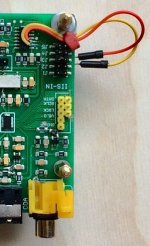
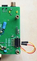
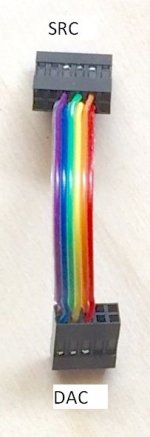
Some pictures showing how the DAC I2S connections were modded to work with the SRC at high speed in order to get the highest sample rates working.
It is not necessary to add pins and sockets, rather ribbon cable could be soldered in place. The idea is like old PATA disk drive cables, every other wire is a ground conductor with each one individually connected to the ground plane at the board on each end. That way it acts much like coax cable in the the RF transmission line sense, although likely with a little less capacitance. It helps to keep the waveforms of the fast clock pulses and the data signal from becoming distorted across the interconnect.
It is not necessary to add pins and sockets, rather ribbon cable could be soldered in place. The idea is like old PATA disk drive cables, every other wire is a ground conductor with each one individually connected to the ground plane at the board on each end. That way it acts much like coax cable in the the RF transmission line sense, although likely with a little less capacitance. It helps to keep the waveforms of the fast clock pulses and the data signal from becoming distorted across the interconnect.
Attachments
- Home
- Source & Line
- Digital Line Level
- ES9038Q2M Board