Okay then. Let's talk some more about hardware mods. You will need to be able to take control of the I2C bus that the microcontroller uses to control the DAC.
To get you started I will post some pics below of necessary mods to the DAC board. A little later I will post something about an Arduino Shield to work with the DAC board mods.
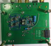
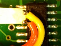
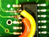
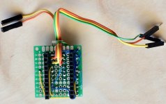
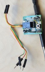
It is necessary to unsolder or lift a couple of pins on the microcontroller that run the I2C bus. There is a data line and a clock line. The pins on the microcontroller are circled in red. Pullup resistors for I2C are in the blue box, just for reference.
On the the bottom of the board a female pin header connector can be soldered on to connect the microcontroller back up, or to connect the Arduino as controller.
Before I do anything to explain about the Arduino and shield, do you have any questions about how to do what is shown in the pictures? (I did describe it in detail earlier in the thread somewhere or other. If you want to see it and can't find it maybe i can write something new.)
To get you started I will post some pics below of necessary mods to the DAC board. A little later I will post something about an Arduino Shield to work with the DAC board mods.
It is necessary to unsolder or lift a couple of pins on the microcontroller that run the I2C bus. There is a data line and a clock line. The pins on the microcontroller are circled in red. Pullup resistors for I2C are in the blue box, just for reference.
On the the bottom of the board a female pin header connector can be soldered on to connect the microcontroller back up, or to connect the Arduino as controller.
Before I do anything to explain about the Arduino and shield, do you have any questions about how to do what is shown in the pictures? (I did describe it in detail earlier in the thread somewhere or other. If you want to see it and can't find it maybe i can write something new.)
Attachments

Regarding DVDD, 1.2v nominal, although there is a an external regulator on some of the boards, Q2M DS says there is an internal regulator. Don't know why they put a regulator on some boards. 😕 The old ES9018 may have needed it.
Isn't external DVDD optional and at given MCLK range external only? It is discussed in the DS later on.
Please so kind and help me:
I like to use PI and the 9038 board Volumio or Moode without resampling, has anybody a solution for that? The DSD and HI res file working fine the 44kHz/16 bit create noise on left chanel only.
Thanks
I like to use PI and the 9038 board Volumio or Moode without resampling, has anybody a solution for that? The DSD and HI res file working fine the 44kHz/16 bit create noise on left chanel only.
Thanks
The DSD and HI res file working fine the 44kHz/16 bit create noise on left chanel only.
Thanks
16-bits might not be enough bits. You might need to Zero Pad the data bits out to the same number of bits as DSD and Hi Res are using. That might require speeding up BCLK.
Maybe try sending it as 22/44 rather than 16/44, if RPI can do that.
Or, maybe try SPDIF or TOSLINK, again, if RPI can do that.
Right, I mixed up with 9018K2M DS, sorry. This digital pin is powered by (some of by 3.3V?!) on all the Chinese 9038Q2M board I listed before excluding Babolcs's blue one (#1306) Is it a hidden feature not documented by ES, or a bad onboard power wiring? Looking forward to see your Ardunio project!Not in the one here. If you find otherwise please send me a PM.
Last edited:
Hi All,
AVCC:
Could someone please model this circuit in Spice regarding noise? (I'm not (yet) enough falmiliar with it)
I merged 3 ideas from the following sources:
1) OPA as power supply
Frans de Wit from diyaudio:
Balanced input all DC coupled RIAA preamp
(The 4th picture where from raw source a clean power source is created.)
2) Walt Jung who used LED in an OPA circuit as VREF
http://www.waltjung.org/PDFs/Walts_Blog_2014_GLED431.pdf
3) And JFET (2SK170) as low noise current source from the SALAS circuits.
Thanks,
Szabolcs
Attachments
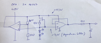
PS.:
1) If you find that the LED still has too high noise it can be simple replace with a resistor, since the constant current source and this R will give a contstant voltage REF.
2) I'm not sure if this circuit will not oscillate at high Freq. (maybe some pF needed perallel with the 510)
1) If you find that the LED still has too high noise it can be simple replace with a resistor, since the constant current source and this R will give a contstant voltage REF.
2) I'm not sure if this circuit will not oscillate at high Freq. (maybe some pF needed perallel with the 510)
The resample of course working, but I like to use without that.
I didn't mean to suggest changing the sample rate or resampling, only to zero pad. With left-justified PCM or I2S one can extend word length by adding zeros to the right up make up the missing bits. But then there are more bits to send in the same amount of time, so BCLK needs to be faster even though LRCK stays the same. Same as if the source material was a longer word size begin with (i.e. 24/44). Sometimes that can be done without resampling. Again, don't know about RPI.
It is just that ES9038Q2M can automatically process SPDIF and TOSLINK, but for I2S or PCM serial audio word length must be specified and the default is 32-bit word length. Also, the microcontroller firmware on the DAC board was not written with any way to change the default I2S or PCM configuration. So, the only options are to redo the firmware or redo how you send I2S/PCM serial audio (if SPDIF/TOSLINK are not options).
Last edited:
PS.:
1) If you find that the LED still has too high noise it can be simple replace with a resistor, since the constant current source and this R will give a contstant voltage REF.
2) I'm not sure if this circuit will not oscillate at high Freq. (maybe some pF needed perallel with the 510)
What makes you think one AD797 output can for sure supply enough current to power another AD797? They use more current than they output, right? How do you keep the second AD797 from oscillating without power bypass caps, and how would those affect loading of the first one? There are lots of other things to think about and consider, some of which won't show up in spice. It would only take a a few seconds to come up with a very different design that is much better if you knew more about engineering. I guess I would say if you like to play around and have fun with circuits you probably have some work ahead of you to learn how to model, build & test, and to learn more about design. It's okay you don't have to be a world class designer right off at the beginning, but you have a lot of work and learning ahead of you. Good luck and hope you have fun along the way.
Last edited:
Looking forward to see your Ardunio project!
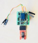
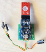
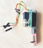
Okay, here it is:
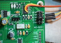
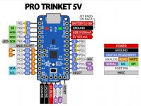
Basically, there are some schottky diodes to protect the Trinket pins from DAC pullup resistors if Trinket power is off. The I2C bus connects to the pins on the Pro Trinket diagram labeled SDA and SCL, I2C data and clock, respectively. Also, important to take note that even though the Pro Trinket diagram is labeled 5v, I am using a 3.3v version to prevent any accidents with mismatched voltage levels.
There is a 3.3v DPDT relay on the shield to seize control of the I2C bus from the DAC microcontroller. Please note I usually use yellow wire for SCL and orange for SDA, but they got accidentally swapped when soldered onto the microcontroller so I swapped them back on the Arduino shield board.
To be clear, to use the shield I unplug the microcontroller from the I2C connector on the DAC board and connect the wires from the microcontroller and the DAC board I2C connector to the orange and yellow wires on the shield. The DAC can be allowed to boot and operate normally from the microcontroller. I can take over at any time with the Arduino, and then return control later. The DAC microcontroller doesn't seem to mind, it just keeps on doing its thing when it is connected.
The shield also has a transistor to drive the relay coil current and a flyback diode across the coil. There is also a button and pins for 2 pots in case I want to control volume or something using the Arduino and a pot.
The little red board is an FTDI interface which is a complication of using a Trinket and wanting real-time terminal interaction with a computer. It takes an FTDI board to do that. More powerful Arduino types don't require that but none run at 3.3v. I could have used a more powerful Arduino and a level translator for the I2C bus, but this is how it ended up. (In theory the level translator might not have been needed, but there are some conditions where an accident could occur without it.)
It may be worth noting that if using an SRC4392 it can also be controlled using the same I2C bus since it is located at a different bus address than the ES9038Q2M.
Attachments
Last edited:
What makes you think one AD797 output can for sure supply enough current to power another AD797? They use more current than they output, right? How do you keep the second AD797 from oscillating without power bypass caps, and how would those affect loading of the first one? There are lots of other things to think about and consider, some of which won't show up in spice. It would only take a a few seconds to come up with a very different design that is much better if you knew more about engineering. I guess I would say if you like to play around and have fun with circuits you probably have some work ahead of you to learn how to model, build & test, and to learn more about design. It's okay you don't have to be a world class designer right off at the beginning, but you have a lot of work and learning ahead of you. Good luck and hope you have fun along the way.
Hi Mark, thanks for your comments. Meanwhile I installed LTspice and trying to do the modelling.
I'm sure 1 opa can power the other - this was in the build of FwD. Since this is only a starting point of common thinking definitely some filter CAP are missing, I think the best if I open a separated post only for this ultra low noise OPA based VREF.
I'm sure 1 opa can power the other - this was in the build of FwD.
I think you may find it depends on how much current the 2nd one needs to output, for one consideration. If it is putting out near maximum at any time, then it may need to pull more than maximum of the one acting as the supply, assuming both are the same type of opamp.
In other words, whoever designed the example you are referring to probably checked to make sure it wouldn't be a problem for that particular design. Doesn't mean it can't be a problem for your design.
Okay then. Let's talk some more about hardware mods. You will need to be able to take control of the I2C bus that the microcontroller uses to control the DAC.
To get you started I will post some pics below of necessary mods to the DAC board. A little later I will post something about an Arduino Shield to work with the DAC board mods.
It is necessary to unsolder or lift a couple of pins on the microcontroller that run the I2C bus. There is a data line and a clock line. The pins on the microcontroller are circled in red. Pullup resistors for I2C are in the blue box, just for reference.
On the the bottom of the board a female pin header connector can be soldered on to connect the microcontroller back up, or to connect the Arduino as controller.
Before I do anything to explain about the Arduino and shield, do you have any questions about how to do what is shown in the pictures? (I did describe it in detail earlier in the thread somewhere or other. If you want to see it and can't find it maybe i can write something new.)
Ok. I know what you are suggesting. Controlling es9038q2m through i2c with use of Arduino. From what I understand with this mod I will lose onboard digital volume control ... right? It is important for me since my amp does not have atteunator.
Is there any way to flash this onboard digital controler and use one of the pins to turn on/off dpll?
From what I understand with this mod I will lose onboard digital volume control ... right?
There are two possibilities: (1) you can return control at any time to the DAC microcontroller if you want. When you do it can adjust volume. Or, (2) some simple Arduino code and a pot attached to one of the pin headers on the shield can control volume exactly the same way that the microcontroller on the DAC board does, which is to say, by writing to some DAC registers to control the volume.
Also, there is no flash memory in the ES9038Q2M and none that we can use in the DAC board microcontroller. I suppose it might be possible to overwrite all the memory in the DAC microcontroller with your own program, but then you would need to write a complete DAC control program. (Usually they are programmed to be secure, so that the original code is protected from theft or modification.)
Please bear in mind I warned you it would take some work.
Last edited:
There are two possibilities: (1) you can return control at any time to the DAC microcontroller if you want. When you do it can adjust volume. Or, (2) some simple Arduino code and a pot attached to one of the pin headers on the shield can control volume exactly the same way that the microcontroller on the DAC board does, which is to say, by writing to some DAC registers to control the volume.
Also, there is no flash memory in the ES9038Q2M and none that we can use in the DAC board microcontroller. I suppose it might be possible to overwrite all the memory in the DAC microcontroller with your own program, but then you would need to write a complete DAC control program. (Usually they are programmed to be secure, so that the original code is protected from theft or modification.)
Please bear in mind I warned you it would take some work.
ok. I think now I got what you meant. So if I am after option number one, then it means: pull up i2c from onboard controler, use arduino to send i2c command turning off DPLL (set some register) pull back i2c to onboard microcontroller. As result I will have es9038q2m with DPLL turned off and still benefit from onboard volume control program, right?
If this is so then I am all listening 🙂 Tell me what to do. I have electronic and programming experience. Although I know what is arduino I have never used it so far. No question so far to your posts, they are clear to me: pulling up i2c from onboard controller is doable for me.
Last edited:
I think for volume control in this case it might be just as well to control it from Arduino. I use the same volume pot, just unplug it from the header on the DAC board and plug it into the shield header.
Also, that's just the way I have it set up now. It should be equally possible to read the pot while it is still connected to the DAC board. The only thing we need to be careful about is not burning up inputs on these 3.3v devices while they are powered off at the same time as whatever else we have them connected to happens to be powered on. Easy enough to do though, we just have to think about it when interfacing.
However, I think it would be a good idea for you to see about getting a data sheet for ES9038Q2M. Normally, it is just a matter of contacting the distributor for your location and asking them to email you the NDA form. You fill it out and they send it back to ESS who then make a copy of the data sheet with your name on it. If there is a leak no question where it came from. Thing is you will be able to enjoy the use of your programming skills more if you have a copy, and I won't have to worry about saying more than is allowed to you. Also, I could use somebody else in this thread who can program too, you know. 🙂 (same for anyone else who would be interested in programming )
)
I should probably also make clear at this point that there would be a bit more to do than just turn of DPLL. There are probably a few registers that would need some configuration. Going into 128_fs mode, setting I2S/PCM format, turning off ASRC/DPLL are all things that may have control bits at more than one register address. Not hard though, I am just saying it is more than one bit. Also, I don't think any of those are bits the DAC microcontroller messes with after the jumpers are set to I2S, but I could be wrong or maybe I missed something. I don't expect that would cause any problem, but if so it just means we would leave the Arduino in control and use it to adjust volume while in that mode. Just want to make clear I haven't done exactly what you want to do yet so I can't promise what I don't know about.
BTW, if anything happens to cause a pin to break off the of the microcontroller please let me know. It would probably be fixable and I could explain about how to do it.
Also, that's just the way I have it set up now. It should be equally possible to read the pot while it is still connected to the DAC board. The only thing we need to be careful about is not burning up inputs on these 3.3v devices while they are powered off at the same time as whatever else we have them connected to happens to be powered on. Easy enough to do though, we just have to think about it when interfacing.
However, I think it would be a good idea for you to see about getting a data sheet for ES9038Q2M. Normally, it is just a matter of contacting the distributor for your location and asking them to email you the NDA form. You fill it out and they send it back to ESS who then make a copy of the data sheet with your name on it. If there is a leak no question where it came from. Thing is you will be able to enjoy the use of your programming skills more if you have a copy, and I won't have to worry about saying more than is allowed to you. Also, I could use somebody else in this thread who can program too, you know. 🙂 (same for anyone else who would be interested in programming
)I should probably also make clear at this point that there would be a bit more to do than just turn of DPLL. There are probably a few registers that would need some configuration. Going into 128_fs mode, setting I2S/PCM format, turning off ASRC/DPLL are all things that may have control bits at more than one register address. Not hard though, I am just saying it is more than one bit. Also, I don't think any of those are bits the DAC microcontroller messes with after the jumpers are set to I2S, but I could be wrong or maybe I missed something. I don't expect that would cause any problem, but if so it just means we would leave the Arduino in control and use it to adjust volume while in that mode. Just want to make clear I haven't done exactly what you want to do yet so I can't promise what I don't know about.
BTW, if anything happens to cause a pin to break off the of the microcontroller please let me know. It would probably be fixable and I could explain about how to do it.
Last edited:
No question so far to your posts, they are clear to me: pulling up i2c from onboard controller is doable for me.
Okay, good. Maybe it would be good for you to go ahead and prepare the DAC board mods as shown in the pictures a few posts ago (or however you would like to do it).
At the same time, if you want to do it more or less the same way I did then you might want to look into getting a '3.3v Pro Trinket' Arduino along with an FTDI adapter. The adapters can either be a little board like the red one I have, or the electronics can be built into a cable. You will need USB cables one way or the other for the Arduino and for the FTDI board. In some cases it may be necessary for both to be powered at the same time (more on that later).
Also, I should mention that Arduino's only come with straight pin headers which you can solder on or not. I used my own right angle header pins for use with the FTDI adapter. Straight would be okay too, just need to make sure there is clearance for it at the end of the shield board. In addition, I should also mention that mounting a shield board directly on the Arduino is not required, it is just a common way to mount interface boards which in Arduino-speak are called shields. Also, maybe helpful to know that programs or reusable modules of programs are often referred to as 'sketches.'
Then you may also want to think about how to lay out your shield and what relay you want to use, if you want to use one, etc.
For those new to Arduino, they have many more I/O functions than pins, so we might say the pins are overloaded with functionality. The pins I used for I2C are ones that may be supported by internal timers in the chip for that purpose. The other three inputs I connected up on my shield for a button and two pin headers for pots all go into pins that can be used as analog inputs. The analog inputs have 10-bit ADCs that can be used to read whatever you want, so long as the voltage doesn't go above Vcc (3.3v in this case) or below ground. The pins are software configured to act as analog inputs. I don't want to get too much more into Arduino particulars yet, I only want to provide a little introductory info that may help with understanding about how to interface and connect external hardware.
Last edited:
DVDD supply
There is a mistake on ver 1.04, 1.06 9038Q2M boards. There is no need of an external 1.2V at the DVDD supply pin. Because the DVDD is internally supplied, the DVDD regulator must be decoupled only to GND with a recommended 4.7 uF X5R capacitor. Thanks to MARK and to the datasheet 🙂.
There is a mistake on ver 1.04, 1.06 9038Q2M boards. There is no need of an external 1.2V at the DVDD supply pin. Because the DVDD is internally supplied, the DVDD regulator must be decoupled only to GND with a recommended 4.7 uF X5R capacitor. Thanks to MARK and to the datasheet 🙂.
- Home
- Source & Line
- Digital Line Level
- ES9038Q2M Board