MAX6126 is a good substitute, but honestly, you can use any reasonable reference, just filter it well, with a passive filter before you send the voltage to the opamp.
MAX6126 is noisy as hell compared to ADM7154-3.3 The Maxim part has 35nV/rtHz @1KHz (at best) while the ADM7154 has 1.5nV/rtHz, see the data sheets. ADM7154-3.3 is less noisy compared to the LTC6655 reference, and also slightly better than the LT3042/3045 (2nV/rtHz). ADM7154and LT304x do not need a buffering op amp.
ha!! syn08 🙂 see, this was typed last night (before your reply, as an addendum.) the first bit, anyway, as I have limited time to give to the threads at the moment. forgive me while I touch it up
Yep, because 6655, or 6126, while quality parts, are not historically low noise and at $12 a pop for the tight tolerance parts (which does not necessarily mean much for this purpose anyway). for the 3v3 analogue voltages (AVCC/XO ), as long as the channels match and the dac reference is something like 3v3, we're happy. Noise is not low enough to use directly for this purpose. it needs filtering regardless of what IC reference you use. active, passive, a mix of the 2. an old lm329 has them both beat on spec alone, but I do prefer smd and current parts.
now, today 🙂
I didnt say it was good 🙂 I said it was a good enough substitute, predominantly because I know its available in the same (msop8, wide) package I suspect he wants? I have some 6655 I bought years ago, but the only use they are going to see is in feeding the reference voltage in an LT3040 circuit. I was shocked when I went to buy some more and see they are $12AUD each!!! not at all worth the money IMO, there are many ways to skin that cat that are better than either of those ICs, at least in noise performance. not as convenient of course. Then, of course, you have the excellent IC regulators. 304X the AD you mention etc etc. I wasnt even answering unasked questions yet, just offering a substitute, as requested. 😀. I tend to agree for the most part on the IC vs opamp buffered reference. the only reason left to do it vs the excellent modern ICs would be ... 'just because' hehe.
Last edited:
Topping D90SE has two OPA1612 right next the dac chip that appear to power AVCC. The negative opamp rail appears to be connected to ground. Closeup pic at: Topping D90SE Review (Balanced DAC) | Page 43 | Audio Science Review (ASR) Forum
Of course it has to be a terrible idea 😛
😛
Of course it has to be a terrible idea
😛
Last edited:
the negative rail is connected to ground. its a +3v3 regulator; it doesnt need to swing below ground.
It's likely a money driven decision. 2x OPA1612 are half the price of 4x ADM7154 or LT3042. They will also perform worse in this function compared to dedicated ultra low noise regulators.
Interesting to note the horrible ceramic capacitors used to decouple everything, and the sorry lack of film capacitors in this function. Not to mention the outrageous switching pre-regulators, a direct insult to the Golden Ears.
Interesting to note the horrible ceramic capacitors used to decouple everything, and the sorry lack of film capacitors in this function. Not to mention the outrageous switching pre-regulators, a direct insult to the Golden Ears.
Last edited:
What's your thought on why this is the current "leader of the board" at ASR then, if the AVCC supply is inferior? Are other parts of the implementiation more important (I/V)? Sheer luck?
Note: This is a honest question as we're currently designing a ES9038q2m board and we're planning to use 1612 as the AVCC. If this is not at all important, then I'd like to have that explained, because a 1612 with all the necessary circuitry around it (reference, decoupling, etc pp) is still more expensive than just a 3042...
Note: This is a honest question as we're currently designing a ES9038q2m board and we're planning to use 1612 as the AVCC. If this is not at all important, then I'd like to have that explained, because a 1612 with all the necessary circuitry around it (reference, decoupling, etc pp) is still more expensive than just a 3042...
I would expect that the performance of the OPA1612 based supply is similar to the performance of the ADM7154 and LT3042. And as syn08 points out, it is lower cost for 4 separate supplies.
I have used the LT3042 and it worked fine for my application (the RTX6001 Audio Analyzer).
I have also simulated (but not tried) the OPA1612 based solution. In my simulation the performance is quite good, with output impedance around 1-2 mohm over a large part of the audio band. And the noise is perhaps even lower than with the LT3042. Of course I don't know what capacitor values they used on the D90SE, so my simulation most likely differs from the actual design.
Last edited:
At those levels, the differences between -123dB and -120dB are essentially zero. It's at the very limit of the APx555 used for measurements (and that's the best tool on the planet) so I would not put too much trust in those results.
My problem with an op amp supply is that it's essentially an unregulated supply to feed AVCC, with an op amp having a capacitive load. A dedicated ultra low noise regulator (in particular with Sense) has none of the disadvantages.
I'm not saying OPA1612 would not work properly, it could be as good as any other comparable solution, but to me is a waste of PCB real estate (requires anyway an ultra low noise regulator (since an op amp input RC filter can filter only so much), then the op amp, all with decoupling, RC filtering, etc...) all to what end benefit? I prefer a compact and straight to the point solution, but then I am not an High End Audio designer (thanks God I don't have to make such decisions).
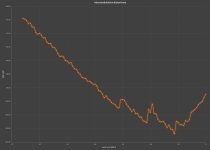
I'm attaching here, for the heck of it, the IMD measurement results for my dual ES9038PRO in Mono mode board, now with a composite op amp (OPA1612+BUF634A). Essentially, IMD is not measurable with my Rohde UPD (and I don't have an APx555). The UPD limit for IMD is some -112dB which is reached at -10dBFS, the jumps are when the instrument changes the scale. As long as the input is under -30dBFS, this board is significantly better than the Toppings D90SE. IMD (7KHz+60Hz) of -100dB is reached at -36dBFS, at the same input level the D90SE has only some -91dB! Using ADM7154 regulators and only X7R 0603 capacitors for decoupling (and lots of them), not a single film cap on the board. The only (poor) excuse for the D90SE is that it's not a dual mono, so the SNR is 3dB lower. You can peek at the new board in my thread https://www.diyaudio.com/forums/equ...trumentation-applications-74.html#post6714832.
One thing I have to admit, my board is a cost no barring implementation, the cost of the board in the photo was about $375 in parts only, while the whole Topping DAC sells for $900, so it would cost probably under half of that, to manufacture. But we are talking about performances here, not prices.
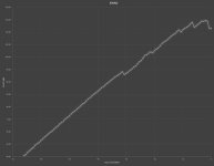
P.S. I include here also the SINAD measurement on my board, -115dB is the Rohde UPD SINAD limit, set by the analog analyzer noise. You could extrapolate the values before reaching the limit, it would be slightly north of 120dB, but only an APx555 could tell precisely (at it's own limit). Sorry, I don't have 30k for one, and not planning to take a second mortgage. The Rohde UPD is basically an AP SYS-2722 equivalent, so one generation in behind.
My problem with an op amp supply is that it's essentially an unregulated supply to feed AVCC, with an op amp having a capacitive load. A dedicated ultra low noise regulator (in particular with Sense) has none of the disadvantages.
I'm not saying OPA1612 would not work properly, it could be as good as any other comparable solution, but to me is a waste of PCB real estate (requires anyway an ultra low noise regulator (since an op amp input RC filter can filter only so much), then the op amp, all with decoupling, RC filtering, etc...) all to what end benefit? I prefer a compact and straight to the point solution, but then I am not an High End Audio designer (thanks God I don't have to make such decisions).
I'm attaching here, for the heck of it, the IMD measurement results for my dual ES9038PRO in Mono mode board, now with a composite op amp (OPA1612+BUF634A). Essentially, IMD is not measurable with my Rohde UPD (and I don't have an APx555). The UPD limit for IMD is some -112dB which is reached at -10dBFS, the jumps are when the instrument changes the scale. As long as the input is under -30dBFS, this board is significantly better than the Toppings D90SE. IMD (7KHz+60Hz) of -100dB is reached at -36dBFS, at the same input level the D90SE has only some -91dB! Using ADM7154 regulators and only X7R 0603 capacitors for decoupling (and lots of them), not a single film cap on the board. The only (poor) excuse for the D90SE is that it's not a dual mono, so the SNR is 3dB lower. You can peek at the new board in my thread https://www.diyaudio.com/forums/equ...trumentation-applications-74.html#post6714832.
One thing I have to admit, my board is a cost no barring implementation, the cost of the board in the photo was about $375 in parts only, while the whole Topping DAC sells for $900, so it would cost probably under half of that, to manufacture. But we are talking about performances here, not prices.
P.S. I include here also the SINAD measurement on my board, -115dB is the Rohde UPD SINAD limit, set by the analog analyzer noise. You could extrapolate the values before reaching the limit, it would be slightly north of 120dB, but only an APx555 could tell precisely (at it's own limit). Sorry, I don't have 30k for one, and not planning to take a second mortgage. The Rohde UPD is basically an AP SYS-2722 equivalent, so one generation in behind.
Attachments
Last edited:
I'll ask again, where do you think these performance improvements stem from? Better/more suitable voltage regulation for AVCC? better decoupling for it? better isolation of EMI caused by digital input signals? grounding? "bigger" DAC chip (I always thought that that would only improve SNR and not THD?!)? Let it out... if you want to. 🙂
Btw. do you plan to release shematics? I particularly am an open source type of guy, but that's not everbody's philosophy here... 😀
Btw. do you plan to release shematics? I particularly am an open source type of guy, but that's not everbody's philosophy here... 😀
The LT3042/5 datasheets barely mention output impedance with no graph of output z wrt. frequency. I suspect that is because it is the devices "Achilles heel". You can deduce that at 50 kHz it has an output z of between 50 and 100mohm from the load transient response but nothing more. Compare that to less than 4 mohm measured for a Jung reg with and AD825. I use OPA1611's and they are better still, roughly equivalent to AD797's with better phase margin.
A standard series regulator has an advantage over LDO's like the LT3042 as it has a low open loop output impedance from an emitter follower output compared with the LDO's high impedance collector ouput. For a given amount of feedback the series regulator can produce a correspondingly lower closed loop output z as a result.
Output impedance is at least as important if the load current can modulate the regulators output voltage to the same degree as the regulators own noise. I've never measured this but I suspect this output z /load current related noise is significant in all regulators feeding AVCC and digital DAC supplies. FWIW I have double blind tested an LT3042 reg vs a Jung Reg on a Katana DAC with my son over many weeks and the Jung based reg was clearly the best. Sadly it is significantly larger to house/locate and more expensive.
John
Off topic I know but those are impressive distortion and SINAD results for that board of yours syn08. Many congrats.
John
John
The output Z side of things was the angle I was coming from as well.
We did extensive simulation with different output caps as well, let me see if I can dig up these graphs tomorrow....
Secondly there was the thought that an opamp output stage would provide a more symmetrical step response as it can source current as well as sink it. If you look at the LT3042 step response graph you can clearly see that it's asymmetrical - no wonder as it can only source current but not sink it.
Why am I speaking only in might/should/would - I'm currently in the process of doing the PCB layouts for our boards. A quite lengthy process of designing all that stuff lies behind us as we're designing a system which will be capable of handling up to 12 channels, with all the hardware and software implications involved, as we're designing a complete system including PC controller software, hardware controller stuff (try sending 7 channels of I2C in a timely manner with an arduino) etc... As I said, I'm an open source kind of guy and certainly all the findings will be released once the hardware is built, tested and listened to...
Last edited:
Off topic I know but those are impressive distortion and SINAD results for that board of yours syn08. Many congrats.
second that.
LT3042 OUTPUT Impedance(2/2): アナログ回路のおもちゃ箱
Above is a link to a Japanese designers site giving graphs of the zout of his various designs of LT3042 regulators. The last graph is one from a linear audio test of different linear regulators. The Jung based regulators are an order of magnitude better on output impedance.
John
Above is a link to a Japanese designers site giving graphs of the zout of his various designs of LT3042 regulators. The last graph is one from a linear audio test of different linear regulators. The Jung based regulators are an order of magnitude better on output impedance.
John
You might want to add more context to your plots like what frequency was this measured at (I presume the ol' 1kHz), measurement bandwidth etc., to make things more comparable and honest... I'd like to see more graphs with all these things mentioned either in the graph file itself ore in the accompanying text
And you also might consider being less triggered by some forum members and their POV here. Let's keep things scientific for the good of it.
Just my 2c 🙂
EDIT: I should wait longer with my replies - that post was targeted at syn08's last post.
And you also might consider being less triggered by some forum members and their POV here. Let's keep things scientific for the good of it.
Just my 2c 🙂
EDIT: I should wait longer with my replies - that post was targeted at syn08's last post.
I'll ask again, where do you think these performance improvements stem from? Better/more suitable voltage regulation for AVCC? better decoupling for it? better isolation of EMI caused by digital input signals? grounding? "bigger" DAC chip (I always thought that that would only improve SNR and not THD?!)? Let it out... if you want to. 🙂
Btw. do you plan to release shematics? I particularly am an open source type of guy, but that's not everbody's philosophy here... 😀
There is absolutely nothing special in the schematic, just the ES9038PRO chips, a horrible Si570 programmable clock with it's horrible close in phase noise, LT3045 standard power supplies for I/V, LT5907 regulators for the digital part, ADM7154 for analog supplies, and the input digital buffers built using TI LMK clock drivers, all in standard data sheet configuration.
The secret sauce? It's in the PCB layout of the 4 layers board, a very compact design. Board size is slightly under 4x4 inch. Switching from OPA1622 to OPA1612 + 2x BUF634A added a few dB in performance, alleged because of the higher current capability, and the lower distortions of the OPA1612, but I am already speculating...
Speculating is not a bad thing, as long as it's not presented as the absolute truth 😉
Can I have your input on how adding up several DAC outputs affects THD? I can comprehend that noise will go down by 3dB by adding 2x the amount of DAC outputs - but what about THD in this regard?
Can I have your input on how adding up several DAC outputs affects THD? I can comprehend that noise will go down by 3dB by adding 2x the amount of DAC outputs - but what about THD in this regard?
- Home
- Source & Line
- Digital Line Level
- ES9038Q2M Board