my experience with increasing /changing AVCC caps to 390uF polymer is an improvement in very low f-range. I guess this is what really takes power to drive from DAC, and so a big reservoir of electrons as written here before might improve this load driving capabilities. But this "more" in deep bass might also sound "slower" as it might cover kick-bass or higher frequencies and though lead to an Impression of a "slower" bass with less dynamics.
I like this deep bass which also could be reason of a bigger stage impression and it was a little missing in my set-up before..anyway tastes are different.
Yes, I took that into account but it is a lesson that I learnt here. That choice of components do in fact affect the voicing and performance tremendously. Initial listening with the HFQs in place looks like the dynamics were restored the modbass bloating is gone but the extension is there now. I am using some refoamed VMPS larger sub arrays. Listening this weekend will tell me what direction to go as I wait for the SEPC OScons. It could be that these cheap caps can indeed swamp out the positives even when paralleled.
I agree, 0.33F overkill. Just give a try to 100uF audio cap like Elna Silmic2 or Cerafine (no OsCons). Even as low as 2x 22 uF/6.3 BG-NX can do some magic. But Mikett's 3042 is also usefull.I fully agree with you.
But 0,33F supercaps might be to mutch.
I have to give it some time.
First it sounded like a big boombox,i never heard that my KT88 tube amps could give that much base 😱 ,but things are setteling,so time wil tel.
Last edited:
Guys, I am aware that Victor was using a different board. However, it appears to look a lot like the mobile versions of ESS DAC chips have similar output current levels. That is, using an 820-ohm feedback resistor in an opamp IV circuit produces around line level output in all of them. Since the DAC outputs are supplied by AVCC, presumably AVCC current is similar as well. In that case, I would expect Victor's results to be pretty similar to results with this DAC if using the same circuitry. That is my working assumption at this point.
Personally, I am using an opamp regulator for AVCC as ESS recommended in the documentation on their downloads page. All opamps in my circuits are LME49720. Those opamps are virtually the same as the opamps used in Benchmark DAC-3, except for maximum voltage rating. A DAC-3 uses +-18v rails rather than +-15.
As I have said before, I do have a DAC-3 here for comparison. I find that if I do all the mods as I have described them the main remaining variable at this point is the quality of the +-15v supply. It is very sensitive to imperfections. I am getting the best results using a well-regulated linear supply for the headphone amp that has also be modified to reduce diode commutation noise that can arise during rectification of AC into DC.
At this point, I am also running the DAC board itself on a Silent Switcher supply. However, I find that Silent Switcher output power quality is very dependent on its input power quality. Noise and EMI on its input seem to come through on its output. Silent Switcher output power quality seems to be best, and DAC sound quality best, if the SS input power source is a well regulated and clean linear 5v supply.
With the best power sources I have available as described above, the ES9038Q2M DAC sounds reasonably close to the DAC-3, including with the headphone amp sound quality as in the project I have been describing in previous posts. Not quite perfectly there yet, but not very far away either. Presumably, putting the Q2M in master I2S mode will help cut the remaiing differences in sound quality between the two DACs.
For those not familiar with DAC-3, it is very similar to the earlier DAC-2 which is on the Stereophile A+ recommended equipment list. They also did a review of DAC-3 and found it to be one of the best few they have ever listened to. Benchmark DAC3 HGC D/A preamplifier-headphone amplifier | Stereophile.com It may also be of interest to know that DAC-3 can be had with an optional internal headphone amp which uses an LME49600, same as the headphone amp I am recommending to mod for use with this DAC project.
So, my subjective opinion is that the Q2M may be capable of near world-class performance if everything else in the circuitry is done perfectly. I only know of two imperfections that cannot be overcome with Q2M and they are (1) output reconstruction and or decimation filter cannot be offloaded to an external DSP such as a Sharc chip, and (2) noise performance is worse than the PRO series DACs 9028 and 9038. In addition, THD is rated at -120dB for Q2M and -122dB for PRO (the distortion number being a best case value if all other circuitry is without flaws).
The cost is reasonable and the performance was wholly unexpected from this board. This is what may stop me from acquiring a serious DAC like the DAC3. I've gotten so much for so little, it makes it hard to shell out much more for the DAC3. Conundrum time.
Now it starts to really get interesting!Have you seen this card before? It looks interesting. Clean power is onboard.
HIFI ES9038Q2M Super DAC +SA8804 + LT3042 regulator SPDIF DSD Output XLR | eBay
I agree, 0.33F overkill. Just give a try to 100uF audio cap like Elna Silmic2 or Cerafine (no OsCons). Even as low as 2x 22 uF/6.3 BG-NX can do some magic. But Mikett's 3042 is also usefull.
I started with 47uF,thats what te most dac,s have,,,to small no soundstage!
Then 180uF,, more than the original 100uF,better base responce more sound.
AVCC needs more uF but how mutch?
I was figuring it out but it went DOA on me.
The cost is reasonable and the performance was wholly unexpected from this board. This is what may stop me from acquiring a serious DAC like the DAC3. I've gotten so much for so little, it makes it hard to shell out much more for the DAC3. Conundrum time.
Seems to me there is maybe a trade-off between spending serious $$$, or spending less $$ and doing a fair amount of work. Maybe it does not seem so much like work if the hobby of building something is fun.
However, if you add up the DIY costs, as we have now maybe it looks like:
DAC Board $40
SRC4392 Board $60
USB to SPDIF Board $25
Headphone Amp Kit $32
Clock upgrade $30
(Silent Switcher ~$100 - optional)
Already up to more than $180 minimum, and still without a complete power supply and other miscellaneous upgrade parts. Also, we aren't quite of the woods yet, we may need an Arduino or another microcontroller when we start looking at Master Mode I2S.
On the other hand, a Benchmark Model DAC3-HGC MSRP (manufacturer suggested retail price) with built-in LME49600 headphone amp and a Remote control is around $2,200.
Maybe we can do pretty close in terms of sound quality with our DIY project for around 10%-15% of the commercial product cost. We will know more over time as things keep moving along.
Speaking of moving along, I may just go with mostly linear power supplies and not try to find a switcher solution for my project. Don't want to have to design one just for this that is clean enough, already enough other work invested. However, would like to get the DAC board off the Silent Switcher and onto the base power supply that also runs the headphone amp in order to keep costs down. Think its probably doable without sacrificing sound quality.
Do keep in mind, my mods are certainly not as extensive as others but considering the improvements and the minimal work. I'm thrilled thus far
Thank you for your answer.
Yes I know, but as it is my first DIYaudio project and I am also novice in electronics, I target simple mods that I can understand for now.
Do you have a reference or a link for your specific high current LT3042?
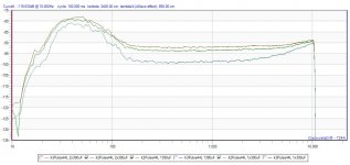
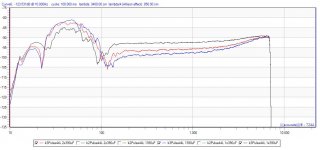
I did some investigation on destortion at output relating to the capacitance value on AVCC. I just compared to the current value of 390uF polymer on board (+1000 uF at the output of my ext. 3,3 reg PSU board).
First to mention, with all cap-values the f-curve was flat (measured with 44.1kHz SPDIF entry and at RCA output with -4dB digital attenuation). This could not be the reason for additional bass impression.
I realized with doubling the on board cap from 1x390uF to 2x390uF the K2 around 20Hz and > 200Hz increased for more than 5dB! At the same time K3 decreases for 3dB >100Hz.
Increasing on board capacity to 1390uF further reduces K3 for 1dB >100Hz and K2 increases only a little for 0,5 dB over total f-range compared to the 2x390uF on board.
I would like now to check the impact the opamp circuit Markw4 recommended. A question to your mods Markw4:
Instead of DVCC you take an extarnal 3,3 reg ?
The entry LP (R-C) is used for both channels, right?
I see a big blue elco for C1 of LP - what is the value?
How to power the opamp? Can I take 15V+ and 15V- of the on-board buffer opamp PS (in ess sheet there is 12V+ against ground plane...)?
Thank you!
Last edited:
Here some measurement pics to above investigation.
Probably the increasing K2 is responsible for the "better" bass performance when increasing cap values..
Probably the increasing K2 is responsible for the "better" bass performance when increasing cap values..
Attachments
Last edited:
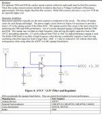
Attached below is information about the AVCC circuit that I used. There is one opamp circuit for the left channel AVCC and another opamp circuit for the right.
However, I only used one input filter that is shared by the two opamps. The filter cap is 10uf.
I mounted the circuit on a little board on the bottom of the PCB and picked up the +=15v from as close as I could down there. It may not be clear from looking at the pictures that I got power from the bottom of the -15v filter cap for the opamp on top of the board which was nearby on the bottom of the board. For the +15v power, I brought it down to that area on the top of the board by repurposing a no longer used trace on top, added more filter caps on top of the board then drilled a hole and brought it out on the bottom near the AVCC circuit. More power decoupling caps were added right at the pins of the dual opamp used for both AVCC circuits.
The input 3.3 voltage was taken from a low noise 3.3v regulator I added just to help keep the analog part of the DAC circuitry more isolated from digital noise and as clean as possible. Whether or not power for the 1.2v regulator should have come from there too or not was a guess since I didn't and still don't have a data sheet.
All the opamps I used were LME49720. Lately, I have been trying +-16v for the opamps. Have to be careful with that. Don't know if it makes any difference yet. But, I am curious since Benchmark uses +-18v and LME49860 opamps.
Attachments

Last edited:
Thank you! So no ceramic caps for C1 (not clear from ess slide).
I still wonder what is the advantage of using this opamp AVCC buffer +3,3V reg. instead of taking 2x 3,3V regs? Does PS for opamp need to be of same high quality as such 2 regs or could it be of lower quality?
I still wonder what is the advantage of using this opamp AVCC buffer +3,3V reg. instead of taking 2x 3,3V regs? Does PS for opamp need to be of same high quality as such 2 regs or could it be of lower quality?
C1 is electrolytic. I edited the previous post a bit. Not sure if you noticed a few minor changes.
Maybe two very clean high-quality regulators could be used instead of opamps, but have to look at it carefully to see if performance would be as good. Without looking at specific regulators and doing some analysis, my guess would be using opamps is preferable.
The reason for using two circuits is to help keep excellent stereo channel separation. Even using two single opamps instead of one dual opamp might help. It can make an audible difference even if one might not think so. Same with using two separate headphone amps, one for each channel. It might seem like overkill but if you compare it with shared circuitry the physical separation can help.
Last edited:
Attached below is information about the AVCC circuit that I used. There is one opamp circuit for the left channel AVCC and another opamp circuit for the right.
However, I only used one input filter that is shared by the two opamps. The filter cap is 10uf.
I mounted the circuit on a little board on the bottom of the PCB and picked up the +=15v from as close as I could down there. It may not be clear from looking at the pictures that I got power from the bottom of the -15v filter cap for the opamp on top of the board which was nearby on the bottom of the board. For the +15v power, I brought it down to that area on the top of the board by repurposing a no longer used trace on top, added more filter caps on top of the board then drilled a hole and brought it out on the bottom near the AVCC circuit. More power decoupling caps were added right at the pins of the dual opamp used for both AVCC circuits.
The input 3.3 voltage was taken from a low noise 3.3v regulator I added just to help keep the analog part of the DAC circuitry more isolated from digital noise and as clean as possible. Whether or not power for the 1.2v regulator should have come from there too or not was a guess since I didn't and still don't have a data sheet.
All the opamps I used were LME49720. Lately, I have been trying +-16v for the opamps. Have to be careful with that. Don't know if it makes any difference yet. But, I am curious since Benchmark uses +-18v and LME49860 opamps.
MarkW4
Just so happens I have one of these in my parts box that I ordered a few months ago, just to have a base dual op amp circuit for whenever I might need one and here it is.
Dual OP Amp Preamp DC Amplification Board PCB for NE5532 OPA2134 OPA2604 AD826 | eBay
If I am correct, it appears easy to redeploy this board into a dual AVCC supply. I have a 317/337 circuit that I initially used so I am good for the dual 15V.
I also have an extra 49720 and some 5532 and also some 2134s that I can try to see as well.
To be clear, I will need to cut the traces to the caps and I can tack on the output of the op amps via AVCC caps from the underside.
I will take the 3.3V feed directly from the LT3042 power supply rather than tapping it close to the other circuits.
My goal is to minimize the amt of invasive mods to the board and get/use premade PCBs via Ebay....My ability to perform SMT and fabbing boards are long gone. So this looks doable.
Last edited:
Thank you for your answer.
Yes I know, but as it is my first DIYaudio project and I am also novice in electronics, I target simple mods that I can understand for now.
Do you have a reference or a link for your specific high current LT3042?
Low Noise LT3042 Linear Regulator Power Supply Board DC Converter Overvoltage | eBay
The above is the link. The board ships with 5V and that is why I initially replaced the 7808 (Ver 1.04) with this power supply. (Ver 1.06) goes directly with the 5V. I tried it and it worked.
To convert the board to 3.3V simply tack a 100K resistor acrosss R1 pad to the ground pad across. This makes for approx 33K paralleled resistance giving 3.3 volts. R1 and R2 are paralleled. It appears the intial designers of the board intended to ship either 3.3 or 5V as assembled.
Seems to me there is maybe a trade-off between spending serious $$$, or spending less $$ and doing a fair amount of work. Maybe it does not seem so much like work if the hobby of building something is fun.
However, if you add up the DIY costs, as we have now maybe it looks like:
DAC Board $40
SRC4392 Board $60
USB to SPDIF Board $25
Headphone Amp Kit $32
Clock upgrade $30
(Silent Switcher ~$100 - optional)
Already up to more than $180 minimum, and still without a complete power supply and other miscellaneous upgrade parts. Also, we aren't quite of the woods yet, we may need an Arduino or another microcontroller when we start looking at Master Mode I2S.
On the other hand, a Benchmark Model DAC3-HGC MSRP (manufacturer suggested retail price) with built-in LME49600 headphone amp and a Remote control is around $2,200.
Maybe we can do pretty close in terms of sound quality with our DIY project for around 10%-15% of the commercial product cost. We will know more over time as things keep moving along.
Speaking of moving along, I may just go with mostly linear power supplies and not try to find a switcher solution for my project. Don't want to have to design one just for this that is clean enough, already enough other work invested. However, would like to get the DAC board off the Silent Switcher and onto the base power supply that also runs the headphone amp in order to keep costs down. Think its probably doable without sacrificing sound quality.
When I started costing out the Buffalo DAC, the cost added up quickly close to 1/2 of a Benchmark. Then I thought, what If I did not like it. The Benchmark might cost more but there is a resale value for it if I moved on and there is the remote, headphone amp that is included as well in the Benchmark. So for the time being I will listen to this "cheap" solution and see where that takes me. So far this solution is "cheap" enough and fun.
The only issue is that for others following the path, someone needs to recommend a good power supply for the analog stage that is superior to a 317/337 and does not cost a lot. I pulled my linear PS out of my old boards bin. What I might do as well is go back to the 317/337 and see if the initial digital supply was the initial weaker stage,
I found some used LH0002 buffers in my parts bin. I wonder if I just buffered the 3.3V feed after the input filter filter, whether this old buffer will be better than the op amp. I think it will be more stable into capacitive loads. Any suggestions?
Mikett, Good idea!
Hopefully, if we can get a few people to try the opamp circuit and report results it may help people better understand the benefits vs capacitor mods. I'm concerned the cap mods are easy but may turn the DAC into an effects box.
Agreed modular solutions make it much easier and more practical for people to implement performance improvement modifications. I can see where the prospect of assembling tiny circuits such as I built would be offputting to a lot of people. Even I wouldn't want to do it again! 😱
I will say that working with tiny parts and working with hot air and so on are things I am getting more comfortable doing as I gain experience. It helps to collect some old circuit boards from old computers or anything with small parts on it. Then experiment, practice, and learn how to remove and replace components. There are also SMT soldering practice kits available. Good stuff, less daunting and more fun the better I get at it.
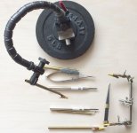
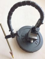
I will post a picture below of a gizmo I made to help with it.
Hopefully, if we can get a few people to try the opamp circuit and report results it may help people better understand the benefits vs capacitor mods. I'm concerned the cap mods are easy but may turn the DAC into an effects box.
Agreed modular solutions make it much easier and more practical for people to implement performance improvement modifications. I can see where the prospect of assembling tiny circuits such as I built would be offputting to a lot of people. Even I wouldn't want to do it again! 😱
I will say that working with tiny parts and working with hot air and so on are things I am getting more comfortable doing as I gain experience. It helps to collect some old circuit boards from old computers or anything with small parts on it. Then experiment, practice, and learn how to remove and replace components. There are also SMT soldering practice kits available. Good stuff, less daunting and more fun the better I get at it.
I will post a picture below of a gizmo I made to help with it.
Attachments
I found some used LH0002 buffers in my parts bin. I wonder if I just buffered the 3.3V feed after the input filter filter, whether this old buffer will be better than the op amp. I think it will be more stable into capacitive loads. Any suggestions?
I would try the ESS recommendations first. They probably did some analysis and testing we may not be equipped to do.
Also, usually buffers use up opamp gain to help achieve low net distortion and produce good performance. As a result, distortion is worse than an opamp alone. That is certainly true of the LME49600 headphone amp or pretty much any power amp.
Mikett, Good idea!
Hopefully, if we can get a few people to try the opamp circuit and report results it may help people better understand the benefits vs capacitor mods. I'm concerned the cap mods are easy but may turn the DAC into an effects box.
Agreed modular solutions make it much easier and more practical for people to implement performance improvement modifications. I can see where the prospect of assembling tiny circuits such as I built would be offputting to a lot of people. Even I wouldn't want to do it again! 😱
I will say that working with tiny parts and working with hot air and so on are things I am getting more comfortable doing as I gain experience. It helps to collect some old circuit boards from old computers or anything with small parts on it. Then experiment, practice, and learn how to remove and replace components. There are also SMT soldering practice kits available. Good stuff, less daunting and more fun the better I get at it.
I will post a picture below of a gizmo I made to help with it.
- Home
- Source & Line
- Digital Line Level
- ES9038Q2M Board