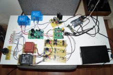
Look wat i dit.
I put in 3 Salas 3,3v shunt,s.
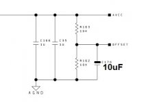
But the biggest improvement came from giving the dac a lot of uF on the
AVCC supply,s.
It went from harsh narrow soundstage to big roomfilling with the biggest base
that wil blow you away.
I am not even thinking about putting in an other opamp,great sound!
Here you can find the story in dutch,but with a lot of pictures.
ES9038Q2M dac streamertje - forum.zelfbouwaudio.nl
@Democles, I have no Salas Regs. Would adding the caps still give the improvement without the Salas? You used .33F supercaps, what is the value of the other (electrolytic? in parallel?) caps? Thanks.
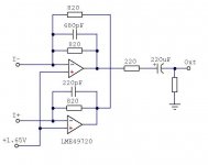
Not Democles, but IIRC, Victor said he added three 1800uf capacitors in parallel with each of the existing AVCC caps. He soldered them onto the existing caps at their terminals on the back side of the circuit board. He also designed his own opamp IV stages and posted the schematic in another thread. The schematic is copied to a fairly recent post by me in this thread, within maybe the past week. His measured performance was very, very good.
Last edited:
actually Victor did that for a different board - ES9018k2m :
tantalum one was 10uF. i do not know how much different ES9038q2m analog part is.
i believe shunt regulators are not supposed to have so huge capacitance in front of them. this was somehow discussed in one of the ES9018 threads regarding Trident regulators.
in general it is not so clear for me what is the principal advantage of discrete shunt/serial regulators over integral LDO regulators for AVCC. most likely not the noise value. current flow handling then?
DVCC - without changes. AVCC has 3 x 1800uF capacitors in parallel with the onboard tantalum capacitor.
tantalum one was 10uF. i do not know how much different ES9038q2m analog part is.
i believe shunt regulators are not supposed to have so huge capacitance in front of them. this was somehow discussed in one of the ES9018 threads regarding Trident regulators.
in general it is not so clear for me what is the principal advantage of discrete shunt/serial regulators over integral LDO regulators for AVCC. most likely not the noise value. current flow handling then?
@Democles, I have no Salas Regs. Would adding the caps still give the improvement without the Salas? You used .33F supercaps, what is the value of the other (electrolytic? in parallel?) caps? Thanks.
I don,t know.
Did the mods all together.
Adding more uF to the AVCC (2x) gives the sound a lot more room and base performens.
The sound of my bord is stil changing.
I have to give it some time.
The cap,s in parallel are 180uF,but by adding the 0,33F supercaps les might be
better.
But giving the AVCC its own 5v supply,s is a good thing.
I used Salas supply but I think any low noise wil do the job.
I have put a Sallas on the clock supply but that gave no big inprovement.
So doing the 2 AVCC might be enough.
@Markw4 see post 514🙂
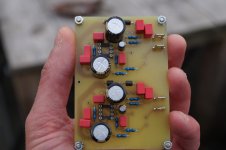
Next step wil be adding a bord with the Victor scematic and hear if it brings something.
Attachments

I have a 1.04
Wow, as MarkW4 said, it appears that it is a lot of work to get this board to a top notch DAC.
However, I am dipping my toes back into digital now. So I wanted to try some simple mods to see where all this is going as a learning experience.
Here are my findings with some mods I performed and something I learned.
First I attached a 15V Linear Supply to the original board 317/337. I had this kicking around. LM317/LM337 Dual Power Adjustable Precision +-1.3V-35V DC Regulator Power Board | eBay
Immediately it was outperforming an Assemblage DAC with the mods dating back to 1999. So it was promising. Next, I then exchanged the power supply with a combination of two.
I removed the 3 terminal reg onboard fed the original power requirements with a Jung modified Sulzer that had been removed from a modified CD player dating back to the late 80s. I then fed the 1117 with the the 317 portion of the previous power supply. Much better sound.
This stayed this way for a few weeks while tried the LME49720. In the end I stuck with the 49720. It sounded slightly better than the 5532. The 5532 seemed to provide better drive but the higher frequencies on the 49720 was better I thought.
Next, I then attached another power supply and removed the dual 317/337 unit. Intending that I was going to put this into a case and I needed a smaller board. The sound went downhill. Suddenly the sound was shrill and the drive was lost. So next I started increasing the capacitance on the 317 output and inputs and this helped quite a bit. Remember this a first time learning experience in messing with digital for myself. I now started to learn the importance of the clean supply in digital. So I ordered this.
Low Noise LT3042 Linear Regulator Power Supply Board DC Converter Overvoltage | eBay
I attached as a 5v output in place of the 8v the 1.04 used and it immediately was a grand improvement. This was something I could live with. It stayed this way for about a week or so. Next I changed the output voltage to 3.3V and then attached the output directly to the 1117 output tab. Now things got really interesting another step up. The improvement in transparency and details was mindblowing to me. The sense of space was now there. Drums thwacks were now so much better. Frighteningly so sometimes. Pianos now sounded so real the dynamics of the keys and force of playing was now so easily perceived.
So I decided to try and improve the AVCC capacitance with some chinese 2200uF caps I had lying around. I simply tacked them on the underside and retained the original caps in place. I listened last night and it was not good...terrible terrible. A lot of smearing details were lost drum attacks were now slow. Pianos sounded dead. Leading edges seemed slow now. They will come off today. Looked into my OLD parts bin and found a couple NOS 330uF panasonic HFQs I will attach today and see. I ordered some OSCON caps to try as well.
Somewhere at this stage I think I am happy enough thus far. It is nowhere as extensive as some of the mods proposed but it is a hobby and for fun and learning with the resources I now have.
I now have this wondering thought. How much better does it get. My turntable will be for sale soon when I downsize my space. I cannot see vinyl getting close to this or am I in for a surprise there as well??? Hmmm.... I could rip out my Jung Super regs out of my preamp that feeds my Bugle RIAA clone and use it instead of the Sulzers.
Last edited:
my experience with increasing /changing AVCC caps to 390uF polymer is an improvement in very low f-range. I guess this is what really takes power to drive from DAC, and so a big reservoir of electrons as written here before might improve this load driving capabilities. But this "more" in deep bass might also sound "slower" as it might cover kick-bass or higher frequencies and though lead to an Impression of a "slower" bass with less dynamics.
I like this deep bass which also could be reason of a bigger stage impression and it was a little missing in my set-up before..anyway tastes are different.
I like this deep bass which also could be reason of a bigger stage impression and it was a little missing in my set-up before..anyway tastes are different.
Guys, I am aware that Victor was using a different board. However, it appears to look a lot like the mobile versions of ESS DAC chips have similar output current levels. That is, using an 820-ohm feedback resistor in an opamp IV circuit produces around line level output in all of them. Since the DAC outputs are supplied by AVCC, presumably AVCC current is similar as well. In that case, I would expect Victor's results to be pretty similar to results with this DAC if using the same circuitry. That is my working assumption at this point.
Personally, I am using an opamp regulator for AVCC as ESS recommended in the documentation on their downloads page. All opamps in my circuits are LME49720. Those opamps are virtually the same as the opamps used in Benchmark DAC-3, except for maximum voltage rating. A DAC-3 uses +-18v rails rather than +-15.
As I have said before, I do have a DAC-3 here for comparison. I find that if I do all the mods as I have described them the main remaining variable at this point is the quality of the +-15v supply. It is very sensitive to imperfections. I am getting the best results using a well-regulated linear supply for the headphone amp that has also be modified to reduce diode commutation noise that can arise during rectification of AC into DC.
At this point, I am also running the DAC board itself on a Silent Switcher supply. However, I find that Silent Switcher output power quality is very dependent on its input power quality. Noise and EMI on its input seem to come through on its output. Silent Switcher output power quality seems to be best, and DAC sound quality best, if the SS input power source is a well regulated and clean linear 5v supply.
With the best power sources I have available as described above, the ES9038Q2M DAC sounds reasonably close to the DAC-3, including with the headphone amp sound quality as in the project I have been describing in previous posts. Not quite perfectly there yet, but not very far away either. Presumably, putting the Q2M in master I2S mode will help cut the remaiing differences in sound quality between the two DACs.
For those not familiar with DAC-3, it is very similar to the earlier DAC-2 which is on the Stereophile A+ recommended equipment list. They also did a review of DAC-3 and found it to be one of the best few they have ever listened to. Benchmark DAC3 HGC D/A preamplifier-headphone amplifier | Stereophile.com It may also be of interest to know that DAC-3 can be had with an optional internal headphone amp which uses an LME49600, same as the headphone amp I am recommending to mod for use with this DAC project.
So, my subjective opinion is that the Q2M may be capable of near world-class performance if everything else in the circuitry is done perfectly. I only know of two imperfections that cannot be overcome with Q2M and they are (1) output reconstruction and or decimation filter cannot be offloaded to an external DSP such as a Sharc chip, and (2) noise performance is worse than the PRO series DACs 9028 and 9038. In addition, THD is rated at -120dB for Q2M and -122dB for PRO (the distortion number being a best case value if all other circuitry is without flaws).
Last edited:
So I ordered this.
Low Noise LT3042 Linear Regulator Power Supply Board DC Converter Overvoltage | eBay
I attached as a 5v output in place of the 8v the 1.04 used and it immediately was a grand improvement. This was something I could live with. It stayed this way for about a week or so. Next I changed the output voltage to 3.3V and then attached the output directly to the 1117 output tab. Now things got really interesting another step up. The improvement in transparency and details was mindblowing to me.
Hi Mikett,
Tell me if I understand it well.
You replaced the 7808 on the board by LT3042 in 5v, then you lowered the voltage to 3.3v to replace both the 7808 and the ams1117 with one LT3042.
Is that right?
I already replace the ams1117 on my board by LT3042 in 3.3v.
So I can desolder the 7805 on my 1.06 and use my LT3042 to replace it and it will improve SQ?
thank you for your help.
Therefore and in reference to my previous post, based on what I have found out and observed so far I am puzzled to find out that other people are reluctant to go ahead and use an opamp regulator for AVCC. It works well and you probably cannot do any better with other approaches in terms of the end result sound quality you can get if everything else I have mentioned is done as close to perfection as possible.
Also, since excellent sound quality results can be obtained with an opamp IV circuit, adding one more dual opamp to regulate AVCC doesn't seem like it should be a big deal. It's pretty easy to do and then you don't have to worry about whether your AVCC power is good enough or not.
Also, since excellent sound quality results can be obtained with an opamp IV circuit, adding one more dual opamp to regulate AVCC doesn't seem like it should be a big deal. It's pretty easy to do and then you don't have to worry about whether your AVCC power is good enough or not.
my experience with increasing /changing AVCC caps to 390uF polymer is an improvement in very low f-range. I guess this is what really takes power to drive from DAC, and so a big reservoir of electrons as written here before might improve this load driving capabilities. But this "more" in deep bass might also sound "slower" as it might cover kick-bass or higher frequencies and though lead to an Impression of a "slower" bass with less dynamics.
I like this deep bass which also could be reason of a bigger stage impression and it was a little missing in my set-up before..anyway tastes are different.
I fully agree with you.
But 0,33F supercaps might be to mutch.
I have to give it some time.
First it sounded like a big boombox,i never heard that my KT88 tube amps could give that much base 😱 ,but things are setteling,so time wil tel.
Have you seen this card before? It looks interesting. Clean power is onboard.
HIFI ES9038Q2M Super DAC +SA8804 + LT3042 regulator SPDIF DSD Output XLR | eBay
HIFI ES9038Q2M Super DAC +SA8804 + LT3042 regulator SPDIF DSD Output XLR | eBay
xlisec, That card looks like they spent a little more money making it as compared to the DACs we have been talking about modding. From what I can tell by looking at the picture, my biggest concern would have to do with the clocking. A high-quality ultra-low jitter 100Mz clock would allow the DAC chip to perform best especially for very high sample rate modes. Obviously, at the asking price of the card, they can't include a really good clock. Also, from looking at the picture it might be hard to upgrade to a normal type of suitable clock. It looks like they are clocking through the SPIDF decoder chip rather than directly into the DAC. Don't know all the details of what they have done, but suspect jitter may be worse than you would want and likely hard to fix properly.
It does look like they have used opamp regulation for AVCC which is a good thing.
If you or somebody does buy one, some close-up pictures of both sides of the board so we can read part numbers and trace interconnections would probably give a much more clear idea of how it works.
It does look like they have used opamp regulation for AVCC which is a good thing.
If you or somebody does buy one, some close-up pictures of both sides of the board so we can read part numbers and trace interconnections would probably give a much more clear idea of how it works.
Mark, thank you for professional info from one picture 🙂. I own "old" 9038q2m v1.04 card. I try some mods in future. This card is not for me. I need I2S interface. My post is only tip.
sorry to hear that. what did happen?
I wanted to take out the supercaps and i made a short.
After, it locked but went to Hifi heaven.
Hope people here have more succes
Oh no! I was so keen on reading your test results after switching to current stage...
What a pitty! I feel with you...
What a pitty! I feel with you...
Doh! Now I wish I'd bought the remote version^^. I hope a universal apple control works with my version. Bought a 3 dollar clone remote now so fingers crossed that is works! I wonder if its possible to find the original enclosure for it too?
Iancanada has developed a nice controller, which works fine with chinese 9038Q2M too. There is a more chance to get it work, than the 3 dollars one. I am lookong forward to get it. His post is here:
ES9018K2M, ES9028Q2M, 9038Q2M DSD/I2S DAC HATs for Raspberry Pi
Last edited:
Hi Mikett,
Tell me if I understand it well.
You replaced the 7808 on the board by LT3042 in 5v, then you lowered the voltage to 3.3v to replace both the 7808 and the ams1117 with one LT3042.
Is that right?
I already replace the ams1117 on my board by LT3042 in 3.3v.
So I can desolder the 7805 on my 1.06 and use my LT3042 to replace it and it will improve SQ?
thank you for your help.
Yes, that is what I did do. DO note that the Lt3042 board I used includes a rectification stage and also has a higher current capability than just a normal 3042. The improvements were incremental in each stage but the largest bang was completely bypassing the 1117.
Do keep in mind, my mods are certainly not as extensive as others but considering the improvements and the minimal work. I'm thrilled thus far
- Home
- Source & Line
- Digital Line Level
- ES9038Q2M Board