Doing sims and measurements can catch a lot of things but I don't believe it catches them all, at least not the way it is commonly done now.
This is not my field of expertise, I find it interesting and I follow as best I can.
But with my field of expertise, a gentleman who runs a tire test lab once told me:
All models are wrong, but some are useful
I’m pleased to see that you recognize simulation isn’t a catch all end all. In the threads I’ve read, that is an unusual position.
I just want to view bith depth and sampling rate on the screen
Registers 66-69 contain the value of 'DPLL Number' which is gives the received sample rate in terms of MCLK. If you know the MCLK frequency, then you can calculate sample rate using the formula on page 43 of the data sheet.
It may also be possible to read SPDIF sample rate and bit depth from the SPDIF channel status bits in registers 70 - 93.
For PCM bit-depth it looks like maybe you could find that out by muting the dac output and quickly trying each manual mode bit-depth setting in register 1, then check lock status in register 94 to see if only one particular bit-depth is able to lock. Most people probably don't bother with that and just use the auto-detect capability to let the dac determine the bit depth from the ratio of the frame clock frequency and the bit clock frequency. Maybe the easiest way to get I2S bit-depth is if the USB board or XMOS chip provides that information. Also, some USB boards send everything to the dac in 32-bit format regardless of the bit-depth of the original file. Any missing low order bits are just filled in with zeros.
EDIT: In addition to what you can get from the dac chip, the USB board F0 through F3 signals can be useful to look at.
Last edited:
Just a quick few queries about the 9038Q2M .... wouldn't the "PRO" version of the 9038 be a better choice for a DIY project than the Q2M (this is the mobile and budget version of the 9038, correct?)
For all the effort a DIY dac processor project entails, isn't it wiser to start off with a HQ part to begin with? I assume swapping in a 9038PRO for this thread's Q2M project is not trivial.
For all the effort a DIY dac processor project entails, isn't it wiser to start off with a HQ part to begin with? I assume swapping in a 9038PRO for this thread's Q2M project is not trivial.
This is a diy project based on a particular board using the 30-pin 'Q2M as opposed to a scratch built design so swapping in a 64-pin 'PRO is not viable. OTOH, with the now easily available chip and data, there is nothing to stop you starting a design based on the PRO. Perhaps more so with the AK4499 on hiatus and the Rohm chip nowhere in sight.
Last edited:
Hi, this is my first post in this forum. I have a short question: Do any of you have any experience with this ES9038Q2M board?
ES9038 Q2M DAC DSD Decoder Support IIS DSD 384KHz Coaxial Fiber DOP | eBay
So after three years, 6,264 replies and 996,905 views is that still the ES9038 board to buy? Is there a better one? Or does that one have a really good layout/design and output section?
ES9038 Q2M DAC DSD Decoder Support IIS DSD 384KHz Coaxial Fiber DOP | eBay
Registers 66-69 contain the value of 'DPLL Number' which is gives the received sample rate in terms of MCLK. If you know the MCLK frequency, then you can calculate sample rate using the formula on page 43 of the data sheet.
It may also be possible to read SPDIF sample rate and bit depth from the SPDIF channel status bits in registers 70 - 93.
For PCM bit-depth it looks like maybe you could find that out by muting the dac output and quickly trying each manual mode bit-depth setting in register 1, then check lock status in register 94 to see if only one particular bit-depth is able to lock. Most people probably don't bother with that and just use the auto-detect capability to let the dac determine the bit depth from the ratio of the frame clock frequency and the bit clock frequency. Maybe the easiest way to get I2S bit-depth is if the USB board or XMOS chip provides that information. Also, some USB boards send everything to the dac in 32-bit format regardless of the bit-depth of the original file. Any missing low order bits are just filled in with zeros.
EDIT: In addition to what you can get from the dac chip, the USB board F0 through F3 signals can be useful to look at.
Hello Mark;
For sync operation,
Lets say i am using 22.5792Mhz clock as default and in case of incoming i2s sampling rate 192khz (24.576MHz series).
Can i also use this FSR information to mute and switch between 22.5792Mhz to 24.576MHz clocks, or it is too late and it must be trigered from usb card?
Last edited:
Just a quick few queries about the 9038Q2M .... wouldn't the "PRO" version of the 9038 be a better choice for a DIY project than the Q2M (this is the mobile and budget version of the 9038, correct?)...
The datasheet specifications of both chips are almost exactly the same. The pro version is claimed to have 2dB better distortion. Pro is rated at -122dB and Q2M at -120dB. Not much difference.
The bigger difference is that pro has 8-channels, and those channels can be paralleled to produces a stereo pair, which can reduce noise by 6dB. The problem with pro is the AVCC current is very high. AVCC PSRR is zero, there is no power supply rejection. Designing a good sounding higher current AVCC regulator is not trivial to do well. I know there are people that will throw a couple of LT3042 or LT3045 at the problem and call it done. IME that isn't the path to best sound quality. Much easier to deal with AVCC requirements if using Q2M. ES9028PRO fits somewhere in between the two 9038 versions in terms of AVCC requirements.
One nice thing about both of the pro versions is that the interpolation filter length can be doubled if operating the dac in stereo mode rather than 8-channel mode. However, one has to come up with one's own coefficients in that case.
So after three years, 6,264 replies and 996,905 views is that still the ES9038 board to buy? Is there a better one? Or does that one have a really good layout/design and output section?
The boards used in the thread sound awful to me in stock form. They are very cheaply designed. The one good thing about them for modding is the PCB layout. The ground plane on the solder side of the board is nearly continuous and unbroken. Close enough anyway. That makes doing a decent job of several good mods possible.
For sync operation,
Lets say i am using 22.5792Mhz clock as default and in case of incoming i2s sampling rate 192khz (24.576MHz series).
Can i also use this FSR information to mute and switch between 22.5792Mhz to 24.576MHz clocks, or it is too late and it must be trigered from usb card?
In synchronous mode the USB board and the dac chip must be sharing the same set of clocks. In other words, the dac chip and the USB board must be exactly synchronous with each other. If the wrong clock is sent to the USB board, the music may play at the wrong speed. So, it is necessary for the USB board to control which clock is used. The USB board gets that information from the PC, since the PC can read the sample rate information in, say, for example, the wav file header.
The boards used in the thread sound awful to me in stock form. They are very cheaply designed. The one good thing about them for modding is the PCB layout. The ground plane on the solder side of the board is nearly continuous and unbroken. Close enough anyway. That makes doing a decent job of several good mods possible.
Yikes. Well I didn't buy it yet. Can you post a picture and link of the best board that you would recommend?
The best board I would recommend? It would probably be a very expensive one 🙂 Assuming that's not actually what you want, maybe you could clarify how picky you are about sound quality and what budget you have set for this? Fairly decent bargain boards probably start at about $100, and go up from there.
Last edited:
I am currently havng a look at the inside of a friend's DAC. It has 9038 PRO and they are using ES9311 to power it. Not too expensive that one, makes sense, but not easy to implement DIY.
Ain't cheap though, plus needs also some PS rejection before that regulation IMHO if having SMPS etc.
Claude
Ain't cheap though, plus needs also some PS rejection before that regulation IMHO if having SMPS etc.
Claude
The best board I would recommend? It would probably be a very expensive one 🙂 Assuming that's not actually what you want, maybe you could clarify how picky you are about sound quality and what budget you have set for this? Fairly decent bargain boards probably start at about $100, and go up from there.
Well I have been pretty happy with the PCM1794 implementation inside a Denon AVR3805 (and 3808) but after building half a dozen power amplifier projects and trying the LJM CS4398 DAC and also an ES9028Q2M DAC I am interested in seeing how much more of an improvement can be made with a better DAC. I also have PCM1704 inside other Denon equipment.
If I am spending the money on Sanken output transistors it might make sense to investigate the DAC more.
But it is difficult for me to determine how much of the budget should go to the DAC without understanding what is the payback and reason to go with $200 instead of $100 instead of $50 DAC.
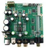
For example, I have attached pictures of a $50 ES9038Q2M. It would be helpful for me to understand where it is deficient and what needs to be improved. Is it the op amp on the output? The layout around the op amp? Grounding? Capacitor placement? The capacitors themselves? Is it the layout around the ES9038Q2M? The bypassing of the ES9038Q2M? Is it the power supplies? Are they too noisy?
I see many $40 to $100 boards but not many above $100. (At least where I am looking.)
What would you recommend in the $100 to $150 range and how is it better than the best choices in cluttered $40 to $100 range?
Attachments

Kozard,
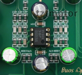
The pics you posted in your last post are of a board I would not want to use. The ground plane on the back of that one is all broken up with traces to light up the LEDs. Too bad about that one.
Regarding the ES9038Q2M board we typically mod in this thread, they need a lot of work to sound better. First couple of mods that give the most improvement are a new add-on output stage, and a new AVCC regulator. Schematics for those can be found attached to post #3003 in this thread. I can give you a link to my dropbox if you want to see an example of how to build the output stage and attach it to the dac board.
After those two mods, dedicated voltage regulators for each of VCCA, DVCC, the clock. Also, a clock upgrade is useful at that point.
Another mod to do at some point is to take control of dac chip registers using an Arduino or other MCU of your choice. Sound quality can be improved considerably by reducing DPLL bandwidth as much as possible, as recommended by ESS. Most cheap dacs leave DPLL bandwidth at the rather high default setting.
Power supplies for the output stage and for the AVCC regulator need acquired. R-core transformer is recommended to powering preregulators, or else maybe sufficient CRCRC filtering, prior to the final output stage, and dac chip and clock, regulators.
The whole thing should go into a well shielded metal box. My preference is to use steel for that.
Last edited:
Kozard,
The pics you posted in your last post are of a board I would not want to use. The ground plane on the back of that one is all broken up with traces to light up the LEDs. Too bad about that one.
Wow. It is a shame to see stuff like that. I bought a CS4398 board (CIRMECH) and found that they had placed the capacitors in pretty arrays and then connected them to the CS4398 and Op Amp using long thin traces. The ground was also a mess. The location and traces for the CS4398 analog supply capacitors was terrible.
Regarding the ES9038Q2M board we typically mod in this thread, they need a lot of work to sound better. First couple of mods that give the most improvement are a new add-on output stage, and a new AVCC regulator. Schematics for those can be found attached to post #3003 in this thread. I can give you a link to my dropbox if you want to see an example of how to build the output stage and attach it to the dac board.
Please send me the link so that I can see.
After those two mods, dedicated voltage regulators for each of VCCA, DVCC, the clock. Also, a clock upgrade is useful at that point.
Power supplies for the output stage and for the AVCC regulator need acquired. R-core transformer is recommended to powering preregulators, or else maybe sufficient CRCRC filtering, prior to the final output stage and dac regulators.
The whole thing should go into a well shielded metal box. My preference is to use steel for that.
What I have done is leave the regulators on board and then build one or more external supplies with LM317/LM337 and GX16 metal aviation connectors. The idea is that the LM317/LM337 are in one metal box and the DAC is in another with a second set of regulators. So only regulated DC is fed to the DAC box. On my last power amp the regulated SMPS power supply is external too (perhaps going too far) and goes through two CLC filter stages before connecting to the power amplifier chassis.
I have used external transformers with cords that came with small mixing consoles to supply the LM317/LM337 boxes.
Last edited:
kozard,
Link is: Dropbox - Output Stage Instructions.zip - Simplify your life
Some people have reported that the .rtf file may get a warning message from Windows. Don't know why. It contains only text and pics for the output stage project. There is nothing executable it it.
Link is: Dropbox - Output Stage Instructions.zip - Simplify your life
Some people have reported that the .rtf file may get a warning message from Windows. Don't know why. It contains only text and pics for the output stage project. There is nothing executable it it.

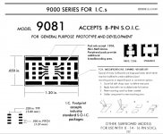
Also considered building the same output stage as above only in SMD. A couple of attachments below may illustrate the concept.
Did anyone do a layout with Eagle or pcbCAD720? It would easily fit in the super cheap 100mm x 100mm size limit specials.
- Home
- Source & Line
- Digital Line Level
- ES9038Q2M Board