Bass notes are now “depth charges” and more detail all round. Thanks Mark
Always good to hear that progress is being made. You are very welcome, of course.
On the other topic you mentioned, Kay and I have been talking about taking control of the dac chip internal control registers using an Arduino microcomputer. The dac boards come with a little MCU (microcontroller) chip included. The MCU programs the dac chip when you move the jumpers, change the volume pot, etc. Unfortunately, the built-in MCU doesn't allow you to do certain important functions, and Kay is the first person besides me to get to the point of wanting to take control of the dac chip in order to get better sound quality out of it.
Last edited:
Hi Mark,
The Sparkfun Level Translator Breakout I used has 1k bypass(pull-up?) resistor on i2c lines. Do we need additional pullup on the dac board?
How to connect the DPDT relay? Is it to turn the MCU power off when connecting the Arduino?
Kay
The Sparkfun Level Translator Breakout I used has 1k bypass(pull-up?) resistor on i2c lines. Do we need additional pullup on the dac board?
How to connect the DPDT relay? Is it to turn the MCU power off when connecting the Arduino?
Kay
Hi Kay,
No, those shouldn't be needed. The existing 4.7k resistors on the board are probably plenty of pullup. I think I would remove the 1k resistors on the dac side of the translator board myself.
Each pole of the DPDT relay is a switch having a 'common' (or pole) with two connection positions (the 'throws'). Each common (pole) goes to an I2C bus line going to the dac chip and pullup resistors. In the default condition, when the relay is powered off (called 'normal'), the dac chip I2C lines should connect through the relay normally-closed pins to the appropriate pins on the mcu. When the relay is powered on (energized) the normally-closed pins become open and the MCU will be disconnected. Since you have the translator, you there is no need to connect it through the relay although you could. If you wanted to connect the translator to the relay, you would connect its appropriate pins to the the normally-open (n.o.) pins on the relay. The relay would then disconnect the MCU when the relay is energized and connect the translator to the dac chip instead.
Because most 3.3v relays draw more current than an Arduino output pin can drive, it is necessary to use a transistor to help. If you Google something like 'use arduino to control relay' you should find explanations of ways to do it. If not, please let me know.
EDIT: Also, a flyback (reverse connected) diode across relay coil terminals is usually good practice and may help prevent problems.
-Mark
Last edited:
Perhaps time for a few more words about AK4499:
Currently clocking the dac with a TP Cronus/Amanero setup using Crystek 957 clocks (22/24MHz are suitable for most purposes, highest PCM sample rates would require faster clocks). No complaints about the sound of clocks so far.
Arduino is still used for I2C register programming since no 32-bit Windows PC here.
Turns out AKM has made lots of provisions on the eval board for trying alternate power supplies for almost all circuit functions needed by the dac chip and eval board, except for one significant thing: the I/V opamps are always connected to the +-15v rails, as are some minimal digital regulators. Since the I/V opamps are OPA1612, as is often the case they tend to sound a little grainy with most +-15v regulators. It does help sound quality to add substantial high quality film caps to the +-15v rails that power the OPA1612's. It also helps to get those digital circuitry voltage regulators, that can be easily be powered from external +5v, disconnected from the +15v rail. Without any modification to the eval board other than moving a few jumpers, just by configuring as described above, it is possible for native 16/44 played on AK4499 to come pretty close to sound quality that is hard to get out of a Sabre dac at DSD512.
At the moment I am not using a differential summing stage, rather the differential line receiver in the Neurochrome HP-1 headphone amp.
Things I would like to investigate include differential summing options, as well as possible use of AD797 for Reference voltage supplies (operating on dedicated +-15v power without film caps). The 37ma or so needed by each 5v reference supply may be pushing luck too far with AD797, but in that case the dac could possibly be operated in a reduced current mode using 22ma Reference Voltage current. So far, have not compared to see if there is any difference in sound quality when operating in the 22ma mode. Presumably, noise may be higher.
Another consideration is that unlike Sabre dacs, AK4499 cannot automatically determine the incoming DSD sample rate. For that reason, sample rate information will probably have to be provided by the USB board then the MCU will need to program the dac chip accordingly. So far, there are no off-the-shelf USB boards I am aware of that can provide incoming sample rate information already galvanically isolated. Amanero may require re-flashing of firmware to make sample rate data available.
Last edited:
So far, there are no off-the-shelf USB boards I am aware of that can provide incoming sample rate information already galvanically isolated.
The diyinhk boards actually do have 4 pins that provide the audio rate (see pics of the back of the board here: y2blog >> DIYINHK XMOS 768KHz USB DDI) and there is an isolated version as well. You can ask for the AK449X firmware to be included and it might just work with the AK4499 if the registers are the same as the AK4495/AK4490 including volume control.
Hi Mark,
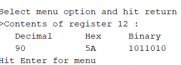
I succeeded lifting the MCU i2c pins. Also succeeded reading the register 12 (snapshot below). Did this direct without the sparkfun by connecting sda,scl & gnd directly to Arduino. Am guessing that sparkfun breakout connection is loose or not working.
The problem I have now is reading and eventually writing the register contents. The readout comes in decimal, hex & binary as shown. Now how do I translate them to the datasheet which does not seem to follow any of the types?
Kay
Attachments
Hi Kay,
Congratulations on successfully lifting the pins! How hard was it?
Also, it is 2:30am here, I will have to write more later this morning. In the meantime, probably best to pull the I2C lines without powering off the dac or arduino. Either one can damage the other, more likely the dac can damage the arduino if one is powered off while the other one is on, due to possible over-voltage on unpowered pins.
Later, I can explain how to protect the chips, and how to understand the bit and byte notations used.
-Mark
Hello,
after modding my two 9038q2m boards and satisfied listening I have lately a strange behaviour on one of them. Right after switching it on, there are several interruptions (sound interrupts very short, but audible as a click and the blue led on board also shortly stops lighting) until the board is warmed up after 2min everything is stable.
I have already changed the PSU for digital and analog, but still the same. Also independent from input source.
Any idea which component to look for with such heat-up behaviour? Can temp changes in winter time (when opening window) cause this by a weak solder point or broken smd capacitor?
Last edited:
How cold was it?
I had a similar problem when leaving an ESS DAC in a non-heated building in the UK in
winter. Plenty of unlocks when cold.
Narrowed it down to the oscillators needing to warm up.
I had a similar problem when leaving an ESS DAC in a non-heated building in the UK in
winter. Plenty of unlocks when cold.
Narrowed it down to the oscillators needing to warm up.
the dac is close to my window. When cold air entered in winter through the window it could have had nelow zero deg. celcius..
So you think it could be the ozcillator? problem remained even now in sommer...
So you think it could be the ozcillator? problem remained even now in sommer...
Probably not in the summer.
Have a look to see if the supply rails take time to stabilise.
Do you have an oscilloscope?
Have a look to see if the supply rails take time to stabilise.
Do you have an oscilloscope?
no oscilloscope...maybe check with a LED+Resistor the 5V supply rail of the clock at start-up for interruptions?
I have already changed the PSU for digital and analog, but still the same. Also independent from input source.
Any idea which component to look for with such heat-up behaviour? Can temp changes in winter time (when opening window) cause this by a weak solder point or broken smd capacitor?
Does the dac have separate voltage regulators for DVCC, VCCA, and clock? MCU?
Could be a problem with a regulator or electrolytic filter cap somewhere. Since it appears to be temperature related and stop when the dac heats up, you might find you have one of those situations where a can of freeze spray can be helpful for troubleshooting. So can a heat gun or solder iron. If you heat up and cool off things one at a time, perhaps you can make the problem come and go at will.
Its also possible that you have a clock or dac chip going bad, of course.
Do you have a scope?
EDIT: Oops! See the scope question was already asked.
Last edited:
Hi Kay,
As I mentioned briefly last night, the risk of connecting a 5v arduino directly to the dac is that both connected chips are only safe when they are both powered on, or both off. If one is on and the other is off, then overvoltage can damage the one that is off.
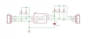
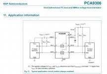
First, maybe we can talk briefly about how the translator is supposed to work. JP2 is supposed to go to the higher voltage device, in the case that would be the 5v arduino board. JP2-4 powers the pullup resistors for that side, and so it should be connected to the Arduino 5v pin in order to power the translator. The dac chip connects to JP1. Looking at PCA9306 datasheet we can see that the JP1 side should also be connected to the local 3.3v power (the MCU 3.3v rail on the dac baord). The only difference is that you removed the pullup resistors on the dac side from the translator board because the dac board already has pullup resistors for that.
All that sound right?
If so, and the translator (PCA9306) is bad, then we need to think a little more about what else we might do for chip safety.
Since the dac board has the only pullup resistors, in theory the arduino can't pullup the dac pins when the dac is powered off. That is, unless perhaps the line in the I2C program that says:
#define I2C_PULLUP 0
were changed to make it equal to 1. In that case the arduino internal pullup resistors would be enabled on the I2C bus lines. Even if the pullups accidentally did get turned on, it still might be okay since the pullups in the arduino are in the range of 20k to 50k ohms (IIFC) and they would make a voltage divider with the dac chip pullup resistors. That would pull down the overvoltage on the dac pins, perhaps to a safe level.
The greater risk might be if dac board is turned on while the arduino is off. In that case dac pullups could overvoltage the arduino pins. I would use reverse connected schottkey rectifier diodes from each of the arduino I2C pins to the the arduino +5v pin. If the dac were turned on first, the schottky diodes would be biased on, and would clamp the I2C pins to less than .3v -.4v or so above arduino VCC. That should be enough to prevent catastrophic damage to the I2C pins.
Is all the foregoing clear, or is there something I missed?
As I mentioned briefly last night, the risk of connecting a 5v arduino directly to the dac is that both connected chips are only safe when they are both powered on, or both off. If one is on and the other is off, then overvoltage can damage the one that is off.
First, maybe we can talk briefly about how the translator is supposed to work. JP2 is supposed to go to the higher voltage device, in the case that would be the 5v arduino board. JP2-4 powers the pullup resistors for that side, and so it should be connected to the Arduino 5v pin in order to power the translator. The dac chip connects to JP1. Looking at PCA9306 datasheet we can see that the JP1 side should also be connected to the local 3.3v power (the MCU 3.3v rail on the dac baord). The only difference is that you removed the pullup resistors on the dac side from the translator board because the dac board already has pullup resistors for that.
All that sound right?
If so, and the translator (PCA9306) is bad, then we need to think a little more about what else we might do for chip safety.
Since the dac board has the only pullup resistors, in theory the arduino can't pullup the dac pins when the dac is powered off. That is, unless perhaps the line in the I2C program that says:
#define I2C_PULLUP 0
were changed to make it equal to 1. In that case the arduino internal pullup resistors would be enabled on the I2C bus lines. Even if the pullups accidentally did get turned on, it still might be okay since the pullups in the arduino are in the range of 20k to 50k ohms (IIFC) and they would make a voltage divider with the dac chip pullup resistors. That would pull down the overvoltage on the dac pins, perhaps to a safe level.
The greater risk might be if dac board is turned on while the arduino is off. In that case dac pullups could overvoltage the arduino pins. I would use reverse connected schottkey rectifier diodes from each of the arduino I2C pins to the the arduino +5v pin. If the dac were turned on first, the schottky diodes would be biased on, and would clamp the I2C pins to less than .3v -.4v or so above arduino VCC. That should be enough to prevent catastrophic damage to the I2C pins.
Is all the foregoing clear, or is there something I missed?
Attachments
Does the dac have separate voltage regulators for DVCC, VCCA, and clock? MCU?
Could be a problem with a regulator or electrolytic filter cap somewhere. Since it appears to be temperature related and stop when the dac heats up, you might find you have one of those situations where a can of freeze spray can be helpful for troubleshooting. So can a heat gun or solder iron. If you heat up and cool off things one at a time, perhaps you can make the problem come and go at will.
Its also possible that you have a clock or dac chip going bad, of course.
Do you have a scope?
EDIT: Oops! See the scope question was already asked.
Hi Mark,
on this board i power like this:
AVCC by opamp, MCU and DVCC by orig. reg, clock by seperate reg.
I had some issue in the past with a defect SPDIF source which ended in strange crack and sizzling noises. could this have destroyed my DAC chip to behave like this?
maybe a good idea to test with a partially applied cold spray if I can reproduce the issue I have at start up. I do not have a scope..
The readout comes in decimal, hex & binary as shown. Now how do I translate them to the datasheet which does not seem to follow any of the types?
Hi Kay,
Data entry to the program is always in decimal, so you have to convert any bit pattern you want to write to a register to decimal format so it can be typed into the program. There is a built-in Windows Calculator that works great for that. You can set it to normal, scientific, or programmer modes. We use programmer mode. You can click on DEC, BIN, or HEX to set the data entry format you want to use. Any numbers entered into the calculator are displayed in all three formats.
In data sheets or sometimes in other documents or books, bits in a word may be described or referred to in style we don't see too often. ESS data sheets might be one example of that kind.
Lets say we see something like:
[7:5]
There are 8-bits in an I2C bus word and they are numbered from left to right starting with the most significant bit, Bit-7 to the least significant bit, Bit-0. The above notation refers to a group of bits ranging from bit-7 to bit-5.
We might also see something like:
4'd0
That type of terminology is seen in the Verilog language. The 4 means refers to a 4-bit vector (a combined group of 4-bits that are used together).
The d means the number that follows will be in decimal format.
The number after the d is the numerical value of the 4-bits.
For example, if we see:
4'd15
We have a group of 4-bits with a value of 15 expressed in decimal. Please see the Windows Calculator image below. If I click on DEC, data entry will be in decimal. If I enter 15 decimal, one can see that the binary bit pattern is 1111. That says 4'd15 represents a set of 4-bits with the pattern 1111, where the leftmost bit is the numerically most significant bit in that group. That pattern can also be represented in hex format by the letter F.
Moving along then, we can think of the 8-bits in an I2C register in different ways. The bits can represent a row of switches where a 1 would represent the switch being turned on, and a 0 indicating a switch is turned off. Or the bits could represent a number used for something. Maybe the bits in a register represent a row of status LEDs we can read out. It could be that some of the bits in a word are switches and other bits are used to represent numbers. Its up to the hardware designers to define the function of each bit.
As programmers, we treat bit patterns as numbers whatever they represent. We decide what switches we want turned on or off, find the 1 and 0 bit pattern for that, type it into the calc and it gives us the decimal number representing that bit pattern which we can type into the arduino program.
Hope the foregoing helps. If not, please let me know if I missed something, or didn't explain well enough.
-Mark
Attachments

Last edited:
AVCC by opamp, MCU and DVCC by orig. reg, clock by seperate reg.
Please don't forget that in addition to the MCU, AVCC, DVCC, and Clock, there is also VCCA. It is the analog power for the RF part of the dac associated with the clock oscillator. The dac will sound best if every one of the above voltages are supplied by independent dedicated voltage regulators. In particular, ESS says the MCU should be on a separate regulator from the dac chip, if you want best sound quality.
I had some issue in the past with a defect SPDIF source which ended in strange crack and sizzling noises. could this have destroyed my DAC chip to behave like this?
Very unlikely. The SPDIF input goes through a little logic chip on the dac board to buffer the SPDIF signal before it goes into the dac chip. If anything would be damaged it would be the logic chip.
maybe a good idea to test with a partially applied cold spray if I can reproduce the issue I have at start up. I do not have a scope..
Cold spray typically comes in a can with an optional thin plastic tube that can be used to direct the spray in a very small area. It is possible to cool one single part at a time in most cases.
Regarding the scope, after a DVM, a scope is the next most widely used instrument in electronics. If you want to do electronics troubleshooting, you are at a great disadvantage not having a scope, its almost like being blind. Definitely worth saving up for the best one you can afford. Even a cheap $15 scope is probably better than no scope at all.
...Without any modification to the eval board other than moving a few jumpers, just by configuring as described above, it is possible for native 16/44 played on AK4499 to come pretty close to sound quality that is hard to get out of a Sabre dac at DSD512...
Listening again this morning with fresh ears causes me to revise the assessment above somewhat. Must have been some ear fatigue yesterday.
At 16/44 with the above configuration, I would say the sound is very slightly brittle at HF. Also, there is a little bit of that PCM sound we tend to get from SD dacs including Benchmark DAC-3. That sound is sort of like a continuous volume modulation of the music at a fast rate, perhaps the volume level being modulated by a buzz, or maybe by a vibration effect. Don't know if anyone else hears it that way. Its something I don't hear with high sample rate DSD.
Regarding some of the above small imperfections, IME, a good differential summing stage with effective filtering would probably help clean it up some and make it sound better than without it.
Having tried to set the record straight above, I will try to get DSD going again with the board otherwise setup as described in the linked post above. More on the sound quality of that a bit later.
- Home
- Source & Line
- Digital Line Level
- ES9038Q2M Board