Output I/V stage (from Topping D10 - ES9018K2M), one channel.
Thank you for posting that. OPA1612 opamps would be more suitable for both I/V and differential summing positions. The MFB differential summing stage is exactly the right idea for low distortion and best sound quality, IME. The impedances around the opamps are may be just about right actually, somewhat lower than what we originally used. I think it would probably be fine to construct an output stage using those component values, so long as resistors are good quality metal film or thin film types, 0.1% tolerance or better. All signal path caps should be good quality C0G or NPO types. Bypass caps X7R ceramic and tantalum. The AVCC to Vref voltage divider could use resistors half the shown values combined with larger filter cap to give a similar time constant. The idea there is to keep dc input resistance as see by both opamp + and - inputs as close to equal as possible to help minimize input distortion due to bias currents. It is essential to build using a good ground plane or best results cannot be obtained. A good +-15v power supply is needed too. If any residual graininess to opamp sound, some large value parallel film caps from +15v to ground and -15v to ground right where power enters the output stage board can very much smooth out that little bit is residual grainy sound, and further help reduce audible distortion.
With that completed, a good AVCC supply is essential. It's effects will be very audible, so it has to be the best you can do.
After that, dedicated voltage regulators for DVCC, VCCA, and Clock. Also, a clock upgrade can be very helpful.
Output leads from AVCC and other local voltage regulators need to be as short and close to dac chip pins as possible. The regulators should be mounted to the dac board ground plane. The bottom side of the circuit board of the particular boards we modify here has a good amount of ground plane real estate that can be put to good use.
One of the last steps is to get an Arduino or equivalent and learn how to program the dac registers. Only with all the above is it possible to get the best sound out of dac chip.
The next step after that would be to make the I2S source quality as good as possible. Many people today are upsampling to DSD256 or DSD512. Sabre and AKM dacs sound much better that way, IME. AK4499 does for example, IMHO.
Last edited:
Thanks for info guys. I’ve already got Andy Weekes super regulators on DVCC, AVCCL and AVCCR and also +-15v for the opamp and I have a PFM FLEA board for clock replacement so next step is output stage
Hi timH,
Looks to me like the super regulators you have should be suitable for +-15, and possibly for AVCC.
On the other hand, DVCC, VCCA, and the clock would probably better benefit from LDO regulators. I used LT1763 (with optional low noise caps) mounted on the back side of the ground plane dead-bug style, for that purpose. (VCCA is power for the oscillator and RF part of the dac chip, which is considered high frequency analog, not digital. Digital switching noise from DVCC should be on a separate regulator). Also, the original 3.3v regulator on the dac board can be retained to power the MCU, which ESS recommends be on a separate regulator from the dac chip.
For AVCC, you may or may not find that our recommended AVCC supply (as shown in post #3003 of this thread) is superior to any other, and you can implement it using two AD797 opamps if you like.
I see that the super regulators you have use AD797 and include pre-regulators (which should be used with that type of supply to sufficiently attenuate line ripple).
The thing of note regarding AD797 is that they don't like to see too much very low ESR capacitance on their power terminals, or they may oscillate. The datasheet shows to use a resistor in series with any decoupling caps over a few uf (don't remember the exact values offhand).
Our experience is also that replacing the clock module with a Crystek 575 100MHz unit helps improve sound quality too (by way of jitter reduction). If you decide to learn how to program the dac chip over I2C bus, and if you then want to run the dac chip in synchronous mode, perhaps better to remove the existing clock in that case and replace it with a u.fl RF connector. That way you can get MCLK from your USB board, FIFO reclocker, or other shared clock source.
Best of luck with your project.
Last edited:
Thanks Mark. The present day ALW super regulators use ad825 for 15v and ad817 for the 3.3v version plus I’ve put a simple cap multiplier in front of each of them. The board I’m using for the clock supply uses an ad797. Here’s the circuit. I will modify the voltage to 3.3v

I’ll read your paragraph about dvcc etc a few more times I think 🙂
I’m sorry I just don’t seem able to post a thumbnail image
I’ll read your paragraph about dvcc etc a few more times I think 🙂
I’m sorry I just don’t seem able to post a thumbnail image
Last edited:
Here's the thing about regulators: Some people can hear very small aberrations in the sound quality of analog audio circuits. Opamps typically have very good PSRR these days, but the PSRR only represents attenuation of power supply audibility, not complete suppression of it. Therefore, for audio circuits sound quality is usually better if we use voltage regulators that sound good. Jung-Didden and other regulators you appear to be using would be of that type.
However, dacs are a different animal from preamps, power amps, phono stages, etc. Dacs include fast digital and very high frequency RF. What makes the HF/RF circuitry sound best in terms of the audio that comes out at the analog end, is low noise and good regulation at frequencies extending well up above the audio band. We don't hear those power supplies in a direct way the same way we hear audio circuit opamp power supplies. It turns out that LDO regulators such as LT1763, ADM7150, LT3045, etc., are simpler, cheaper, and end up sounding as good or better (when used for HF/RF dac functions) than Jung or similar 'audio' power supply regulators do. It is also very important that there be very low inductance between regulators and loads for HF/RF applications. That means the regulators should be mounted directly to dac ground plane, and very short length wires should be used to connect regulator outputs to loads. Having such regulators on other boards is not ideal. Also, having the voltage bounce around very slightly in response to load current variations in nice sounding way for output stages, it not the right kind of little bouncing around in response to load variations that is good for an oscillator or clock divider circuit. LDOs are designed for that exact type of application, just as Jung regulators are designed to sound good with analog audio output stages.
However, dacs are a different animal from preamps, power amps, phono stages, etc. Dacs include fast digital and very high frequency RF. What makes the HF/RF circuitry sound best in terms of the audio that comes out at the analog end, is low noise and good regulation at frequencies extending well up above the audio band. We don't hear those power supplies in a direct way the same way we hear audio circuit opamp power supplies. It turns out that LDO regulators such as LT1763, ADM7150, LT3045, etc., are simpler, cheaper, and end up sounding as good or better (when used for HF/RF dac functions) than Jung or similar 'audio' power supply regulators do. It is also very important that there be very low inductance between regulators and loads for HF/RF applications. That means the regulators should be mounted directly to dac ground plane, and very short length wires should be used to connect regulator outputs to loads. Having such regulators on other boards is not ideal. Also, having the voltage bounce around very slightly in response to load current variations in nice sounding way for output stages, it not the right kind of little bouncing around in response to load variations that is good for an oscillator or clock divider circuit. LDOs are designed for that exact type of application, just as Jung regulators are designed to sound good with analog audio output stages.
Last edited:
Hi guys, I don't know if any of you are on facebook but I have set up a group following my own project of building a Hi-fi (including this DAC). Some of my friends are slowly starting to show some interest. Please feel free to join if it's your thing.
Log into Facebook | Facebook
Log into Facebook | Facebook
Mark, have you ever used or measured the Weekes Jung reg or pcm Flea?
Nope. I have a several power supplies here I want to try out, but so far most of them are still waiting for a turn. There is a Jung-Didden regulator I have running, but I can see that it needs a pre-regulator, something I haven't hooked up yet.
...don't know if any of you are on facebook...
Not me. Happy to help out people with dac modding and related issues here, of course.
i2c register programming
Hi Mark,
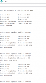
Finally got printout from Serial Monitor using the DAC Sketch you provided. The issue was two-fold. The adding of Softi2cMaster as a zip file as you said, and that the SM baud rate default was 9600. The sketch uses 1200. On setting this, I could access the menu, DAC Control & Configuration.
The first thing I tried was option 1, seize dac. That just gives me printout of the menu again. Is this correct? Should some msg of confirmation be there I wonder? Otherwise am guessing the MCU still blocks the connection.
Then I went to option 7, select register. >Enter register number (decimal)>. Entered 12, got Selected Register (decimal) = 12, Hit Enter for menu. Then tried option 8-read selected, and press enter. It just gives the menu again.
Any thoughts? When you have the time, you must be busy with AK4499 of which your comments are very exciting, further comments eagerly anticipated.
Cheers & Regards,
Kay
Hi Mark,
Finally got printout from Serial Monitor using the DAC Sketch you provided. The issue was two-fold. The adding of Softi2cMaster as a zip file as you said, and that the SM baud rate default was 9600. The sketch uses 1200. On setting this, I could access the menu, DAC Control & Configuration.
The first thing I tried was option 1, seize dac. That just gives me printout of the menu again. Is this correct? Should some msg of confirmation be there I wonder? Otherwise am guessing the MCU still blocks the connection.
Then I went to option 7, select register. >Enter register number (decimal)>. Entered 12, got Selected Register (decimal) = 12, Hit Enter for menu. Then tried option 8-read selected, and press enter. It just gives the menu again.
Any thoughts? When you have the time, you must be busy with AK4499 of which your comments are very exciting, further comments eagerly anticipated.
Cheers & Regards,
Kay
Attachments
Hi Kay,
Yes, the Arduino Trinket boards I use require use of an FTDI board for serial communications, and its baud rate is 1200. 9600 is a more common baud rate for many serial ports (like in the old RS-232, in this case emulated over USB) communication.
If you have not already done it, I would suggest to go into the Arduino compiler preferences and check the box to show line numbers. That makes it easier to find sections of the program sometimes.
When you enter a menu option, such as the example you gave, there should be a cursor in the little one line box at the top of the serial monitor window. That is where you enter text such as menu numbers. The behavior you see is what you get if the program does not recognize that you typed in a valid menu number. In that case it just displays the menu again.
First thing to do would be to make sure an 8 appears in the serial monitor box before you press enter. If not there could be some issue with the keyboard.
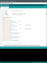
If everything looks okay up to that point then we may have look in the program to find out why it isn't giving a proper response. The menu part of the program can be seen starting around line 85 as shown below. After that, the menu number you type in is read into the program at line 120. It then calls a function at the end of the program to convert the number code you typed in into an INTeger number for evaluation by the CASE statements. The conversion function starts at line 668, etc.
We can print out messages at any point to see what the program thinks its doing. However, my guess at this point is that either an 8 isn't appearing in the input box, or you are using something other than a US keyboard and the character codes are different. Otherwise, the program should get to case 8 at line 224 and print out something other than the menu to the serial monitor display.
Please let me know whatever you may find out and or if you are not sure what to do at any point. I can help you sort through whatever the problem is, most likely.
-Mark
Yes, the Arduino Trinket boards I use require use of an FTDI board for serial communications, and its baud rate is 1200. 9600 is a more common baud rate for many serial ports (like in the old RS-232, in this case emulated over USB) communication.
If you have not already done it, I would suggest to go into the Arduino compiler preferences and check the box to show line numbers. That makes it easier to find sections of the program sometimes.
When you enter a menu option, such as the example you gave, there should be a cursor in the little one line box at the top of the serial monitor window. That is where you enter text such as menu numbers. The behavior you see is what you get if the program does not recognize that you typed in a valid menu number. In that case it just displays the menu again.
First thing to do would be to make sure an 8 appears in the serial monitor box before you press enter. If not there could be some issue with the keyboard.
If everything looks okay up to that point then we may have look in the program to find out why it isn't giving a proper response. The menu part of the program can be seen starting around line 85 as shown below. After that, the menu number you type in is read into the program at line 120. It then calls a function at the end of the program to convert the number code you typed in into an INTeger number for evaluation by the CASE statements. The conversion function starts at line 668, etc.
We can print out messages at any point to see what the program thinks its doing. However, my guess at this point is that either an 8 isn't appearing in the input box, or you are using something other than a US keyboard and the character codes are different. Otherwise, the program should get to case 8 at line 224 and print out something other than the menu to the serial monitor display.
Please let me know whatever you may find out and or if you are not sure what to do at any point. I can help you sort through whatever the problem is, most likely.
-Mark
Attachments
Kay,
A bit more to add to my response above:
The options to seize and release the dac operate a DPDT relay via one of the Arduino output pins. I need that because my dac is not version 1.7 with the ability to stop the MCU using J1, J2. Therefore, I need to take control of the I2C bus away from the MCU and give it to Arduino. If you don't hook a relay like that to your Arduino then those first two menu options won't do anything.
The other thing I wanted to add is that I have been using the Arduino compiler Serial Monitor to talk to the Arduino, not a separate terminal emulator program. At one time I had the programming working either way, terminal emulator or serial monitor, but the menu interface didn't work properly with putty terminal emulator and I didn't get around to fixing it.
Last thing, once you get it talking to the dac, we can go into some other details about using the program. There still may be some issues making sure I2C is fully working, have to see. By the way, there are really cheap and low bandwidth scopes available on ebay for $15 or so. The scopes are good enough to see I2C signals working or not, and to see audio and higher frequencies up to 200kHz or so. Not necessarily enough bandwidth to see an opamp oscillating, or to look at clocks. But for $15, still likely better than nothing. Fully Welded Assembled DSO138 2.4" TFT Digital Oscilloscope (1Msps) + Probe B1 | eBay ...they do need a little power supply, and a 10x scope probe would also be a very good add-on accessory. DSO-Shell (DSO150) Oscilloscope Full Assembled with P6020 BNC Standard Probe 689286393428 | eBay
Last edited:
Hi Mark,
Thanks for your advice. My keyboard is US. I have a sneaky feeling that MCU is not stopping even though board version is 1.07. And i2s lock led is on when connected to xmos even though j1 & j2 are jumped. Am afraid might have to lift the MCU pins.
The oscilloscopes are interesting, I might go for them and learn how to use them so I can check the i2c connection.
Regards,
Kay
I have a sneaky feeling that MCU is not stopping even though board version is 1.07.
Hi Kay,
If the lock light goes on and off when you connect and disconnect the I2S or SPDIF input then the MCU is still working. If the light is just stuck on, its hard to say what is really going on. I have a board that says it 1.07 and the display never worked all, and the MCU never stopped when I put on J1, J2, so I know it can happen.
Before lifting I2C pins, it would be good to have a cheap scope and or a cheap logic analyzer. The cheap logic analyzers are not as fast as they claim, but they always work fine for me for capturing and decoding I2C. They aren't fast enough for I2S, however. USB Logic Analyzer Device Set USB Cable 24MHz 8CH 24MHz for ARM FPGA M100 M434 673275920535 | eBay
If you do have to lift pins and a pin breaks off, its not the end of the dac. You could still operate it with the Arduino. However, you might want to adjust how the program works to make it more convenient to do what you want.
-Mark
Hi Mark,
Yes, when I connect the computer to xmos usb, the lock light comes on, and turns off when disconnected. Ordered the cheap dso138 but will take some time to reach me.
In case I need to lift the pins, will it be right to remove the two resistors between mcu and the dac instead of cutting the traces? And using the i2c connections on the underside of the board?
Kay
..will it be right to remove the two resistors between mcu and the dac instead of cutting the traces? And using the i2c connections on the underside of the board?
You could remove the two pullup resistors, but you will need to somehow add them back into the circuit somewhere, since pullup resistors are needed for I2C bus to work. As far as using the connector on the bottom of the board, IIRC, the vias from that connector come up to the top of the board underneath the MCU chip, then go to the pullup resistors in one direction, and go to the MCU I2C pins in the other direction. From MCU pins, the I2C signals go directly out to the dac chip. If so, that means using the connector on the bottom of the board is only good for connecting more or less directly to the MCU I2C pins, not for connecting to the dac chip while bypassing the MCU.
If its easier you could remove the two SMD pullup resistors, then cut the I2C traces between the dac chip and the MCU chip, then add new pullup resistors going to dac chip I2C pins and also hook up the Arduino to that. In that case, unless you add an I2C seizure relay like I did, then the MCU would remain inoperative until you hooked it back up.
I did one board's I2C hookup more or less that way without doing pin lifting. Posted pictures on how it could be done that way. I think it was harder to do that vs pin lifting, but at least it did not risk breaking off MCU pins.
Always good to practice on one or two junk boards if considering pin lifting. It might help to add some soft leaded 63/37 solder and flux to pins to mix with existing unleaded solder. Or maybe try to use chip quik on the MCU I2C pins. The idea would be to first loosen up and maybe remove most of the hard unleaded solder so that the pins are not to strongly stuck down to the PCB traces. If a problem occurs during pin lifting, it is more common for it to be a torn PCB trace rather than a broken pin. Broken pins usually happen from trying too many times to bend the pin into the new desired position so that it fatigue cracks where most of the stress is where it goes into the chip package. Another thing that breaks pins is trying to make too sharp of an upward bend. Best to free the pin with the least amount of motion, then bend it up one time. Wherever it ends up, leave it and solder a wire to it right were it is. If it has to be moved again, try to do it very gently and make sure the second bend is the last bend. Only move it enough so that a wire can be soldered to it, don't worry if it looks a little crooked or otherwise not pretty.
Last edited:
No idea what you guys are talking about 😉 but on a more mundane note I’ve sort of taken Marks advice and ordered some LT1763 samples from Analog Devices. I couldn’t wait so in the meantime I’ve fitted the PFM Flea regulator to DVCC and can report a nice improvement. Bass notes are now “depth charges” and more detail all round. Thanks Mark
Hi Mark,
It's more complicated than I previously assume. As you allude to, the other functions of the mcu need to be preserved.
Here a wild thought. It would be great if we somehow could let arduino do all the functions, then the mcu can be removed completely. The guys at hifiduino have the code for es9018k2m dac which seem to be completely controlled by remote/rotary encoder( link). If only one could customized it for this dac, it will end up even more proper. And the author said he didn't mind people modifiying it for their purpose.
Kay
Hi Kay,
I don't know about ES9018k2m, I don't have a data sheet for that one. Can't say how programming it differs from ES9038Q2M. However, its pretty easy to see what the existing MCU is doing if you have one of the $10 logic analyzers. You can watch what it does when the dac boots, when you change inputs from I2S to SPDIF, etc. In fact, that is how I first starting figuring out how the dac MCU is programmed. There isn't a whole lot to it, but some other functions need to be added.
There is also Dim Dim's ES9028/ES9038 control project. Isn't there a thread about it around here somewhere? No matter though. Once you figure out how you want to program the dac, its fairly trivial to write an Arduino program to do it. The hard part is figuring out certain technical issues like how to deal with multi-address registers using the Arduino language. It isn't the most sophisticated language for that. Of course, the labor intensive part is writing a nice user interface. Also, learning how to program the chip from the very sparse data sheet also takes some getting used to, there is a learning curve for that.
As far as things like volume control and remote control, those things are pretty trivial. Remote control is a common Arduino project feature, so there are good existing libraries for that. There are also libraries for writing to displays.
Anyway, the program you downloaded can read and write whatever it needs to, so that issue can be considered solved. What would be left would be to automate certain common things you might want to do so you don't have to type in multiple register commands. Pretty easy to make a function that reads a list of register addresses and register contents to write out. Also pretty easy to read registers so as to know when to light up a 'lock' LED and or for other status display functions.
I would encourage you to do some bit-banging with the dac registers using Arduino to start with until you understand how the register functions work. After that would be a good time to decide how you would like to end up in the final state, control-wise.
Also, not a bad idea to try pin lifting first, but up to you. Actually, the ES9038PRO will just run with no register programming required for default operation. However, Q2M is different and will remain silent until one or more registers are configured. In particular, there is the one reg that will keep it muted by default that always needs boot up configuration.
-Mark
Last edited:
- Home
- Source & Line
- Digital Line Level
- ES9038Q2M Board