Are we all talking about this board:
NEW HiFi Assembled ES9028 I2S input decoders ES9028Q2M mill board DAC | eBay
What mods to do for that board?
This thread has mentioned the board in the link above but I'm not sure if we are all talking about it or not..
Thanks
Philip
Mod against the odds
Researching to put them in favour of the modder!
Hi Philip,
Nope. It's the one in my reply a page back before this one: https://www.diyaudio.com/forums/digital-line-level/314935-es9038q2m-board-362.html#post5663452
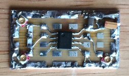
The board you linked to uses a 9028, not 9038. As it turns out a 9028 actually puts out something like 4x more current. That could possibly be okay if you wanted to build an output stage and adjust the I/V resistors accordingly. Another issue might be that I don't have a data sheet for a 9028k2m, so I don't know if the same register architecture exists inside. Also, don't know what the ground plane looks like on the back. If you just wanted to do whatever mods you could, most of the ones we do here would probably work. However, because of the higher output currents, AVCC current would be higher too. Don't know if an opamp regulator would work or not. It might, depending on the particular opamp.
EDIT: To clarify, ES9028k2m puts out more current than ES9038Q2M. However, ES9038PRO puts out more current than ES9028PRO. Guessing here, but most likely they reduced ES9038Q2M output currents to make them more compatible with power requirements for mobile devices. The main advantage of higher current is lower noise, thus better signal to noise ratio. However, noise on ES9038Q2M is low enough for most purposes, spec'ed at -122dB, and the cost of building a dac with one is much less than if using ES9038PRO and going for minimal noise performance. Distortion specs, in contrast, are nearly the same between Q2M and PRO. Q2M is rated at -120dB noise, vs -122dB for PRO.
Nope. It's the one in my reply a page back before this one: https://www.diyaudio.com/forums/digital-line-level/314935-es9038q2m-board-362.html#post5663452
The board you linked to uses a 9028, not 9038. As it turns out a 9028 actually puts out something like 4x more current. That could possibly be okay if you wanted to build an output stage and adjust the I/V resistors accordingly. Another issue might be that I don't have a data sheet for a 9028k2m, so I don't know if the same register architecture exists inside. Also, don't know what the ground plane looks like on the back. If you just wanted to do whatever mods you could, most of the ones we do here would probably work. However, because of the higher output currents, AVCC current would be higher too. Don't know if an opamp regulator would work or not. It might, depending on the particular opamp.
EDIT: To clarify, ES9028k2m puts out more current than ES9038Q2M. However, ES9038PRO puts out more current than ES9028PRO. Guessing here, but most likely they reduced ES9038Q2M output currents to make them more compatible with power requirements for mobile devices. The main advantage of higher current is lower noise, thus better signal to noise ratio. However, noise on ES9038Q2M is low enough for most purposes, spec'ed at -122dB, and the cost of building a dac with one is much less than if using ES9038PRO and going for minimal noise performance. Distortion specs, in contrast, are nearly the same between Q2M and PRO. Q2M is rated at -120dB noise, vs -122dB for PRO.
Last edited:
I have another question. I read that the processor consumes 500mW. The complete working board requires 15v and some use dual 15v inputs.
As designed, the dac board can be operated from a single +12v to +15v supply, or optionally from + and -15 supplies (or +-12v). The 15v rail(s) directly powers the output opamp. Additionally, the +15v rail is dropped through down to 5v (or 8v on some brands of boards), then dropped further to +3.3v by means of linear voltage regulators to run various dac chip functions, the clock, and the MCU. It isn't so much the amount of current that matters so much as it is the amount of power. In the default design, most of the power is turned into heat by the 5v and 3.3v linear regulators.
It is recommended to power the output stage and the AVCC opamp with an external +-15v power supply (possibly with some added film capacitor filtering). A separate +5v supply then would power any and all 3.3v regulators on the dac board, and directly power an LTC6655 voltage reference on the AVCC board. The +5v supply also is used to power the AK4137 board, if included in the build (highly recommended for best sound quality).
Last edited:
What is the difference between the es9038q2m and the es9038pro, other than the price?
I was considering making the pro my next target and wondering how much better it really is. And if the price difference is proportional to the quality difference.
Thanks.
Philip
Modding against the odds
Researching to put the odds in favour of the modder!
I was considering making the pro my next target and wondering how much better it really is. And if the price difference is proportional to the quality difference.
Thanks.
Philip
Modding against the odds
Researching to put the odds in favour of the modder!
Philip,
I answered part of your question about the differences in an earlier edit of my last reply to one of your earlier posts. It should be up a few posts before this one.
Other than things like distortion and noise already mentioned above, Q2M is a stereo dac, and PRO has 8-channels. The way to get the lowest noise from PRO is to configure it in software to run as one stereo dac with four output channels in parallel to make up each of the left and right channels. Every time output current is doubled, noise is reduced by 3dB. Since PRO has more current than Q2M on each channel to begin with, and since PRO has multiple channels that can be run in parallel, noise can be reduced by several dB. However, not clear that having noise way lower than distortion is all that much of a benefit. Most PRO dacs don't parallel all the channels, since noise is usually plenty low to begin with.
In addition, there are different ways in which money and resources can be spent to make a good dac. Getting noise down a low as possible is only one of at least a few possible goals. Just making a dac that actually gets distortion down to what the dac chip specs says is possible is more than most dac manufacturers actually do. Distortion comes from multiple areas, and lots of attention to numerous details is necessary to achieve best sound quality.
One area that can affect distortion, and sound quality in general, is that of power supplies. Making switch mode power supplies that don't adversely affect sound quality is a big issue for many commercial dacs. Any that run from wall wart power would be suspect. For best sound quality at low cost, we don't use switching supplies for this project. Although it is possible to design a clean, and actually superior switching supply, cost and complexity for a good one make it something possibly only practical for dacs up the $2k+ price range, IME.
Mostly, the modded dac design we have here is in pretty good shape. It could probably primarily benefit from further development in two areas: jitter reducion, and interpolation filtering. Both are things that have to be done outside the dac chip. Right now, my focus is on trying to get jitter lower than it is now. We already get pretty low jitter using a Crystek clock and using AK4137 for upsampling. Both things can help reduce jitter, but it is still possible to do better. Although there are some well understood ways of jitter reduction, they usually introduce processing delays or have other limitations. I am hoping to find a solution without the common drawbacks.
Regarding interpolation filtering, one reason for using AK4137 is that besides upsampling it can convert PCM audio to DSD format. In many or maybe most dacs, DSD fitering is easier to make sound good as compared to PCM filtering (at least given the DSP power inside the dac chip). Therefore, we get a second sound quality improvement from using AK4137. The only way I know of to get equally good PCM sound quality would be use external interpolation filtering, which is an option the dac chip can be programmed to allow. The main problem is figuring out how to design an external filter using low cost chips such as Spartan 6, and trying to find low cost development software. There is always a way, I guess, but I don't really want to do a lot of low level VHDL programming.
Last edited:
Markw4. Thanks. I noticed that the 9038q2m uses hyperstream2 like the pro series and is the only DAC, not soc, that esstech offers besides the expensive pro DACs that uses hyperstream2
The ak4137 converting pcm to DSD sounds amazing. I think meridian did something similar in one of their CD players.
I assume that outputs DSD in i2s format. It says standard, low freq and 768k crystal confifs are available. Which one should I get? Which is best? I assume standard...
I am totally buying that ak4137 board and later, probably the 9038q2m.
That's genius, I always prefer purpose built chips to software and much of the pcm to DSD software costs as much or more than that board!
Last edited:
Hyperstream is what all the ESS Sabre dacs use. ES9028 and 38 variants have the latest version. ES9018 was't as good.
Also, ESS has some downloads on their website that you could study to see what they have to say: ESS Technology :: Downloads
There are some youtube videos of Martin Mallinson talking about ESS technology too.
We hook up devices in this order: USB-to-I2S-board -> AK4137 board -> ES9038Q2M board. The AK4137 can be configured as desired using the buttons on the board or the button attached to the display (depending on which type of AK4137 board).
I have recommended using gold flashed or gold plated pin header connectors for I2S between AK4137 board and the dac board to help minimize jitter (it definitely helps). For the low cost AK4137 board, that means the existing output pin header needs to be removed and replaced which can be tricky. I can describe how I did it if anyone is getting close to that point. I also add some extra ground pins for the I2S connections at AK4137 and dac boards. That allows use of ribbon cable for I2S configured as G-S-G-S-G-S-G where ground and signal wires are alternated. u.fl connectors and cables might be another option.
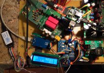
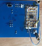
I will attach a couple of pics below showing test setups with both types of AK4137 boards. In the first picture, the thing on the upper left corner of the dac board with the little red board attached to it is the Arduino, it's shield, and an FTDI communication board. The blue board to the left of the dac board is a modded LME49860 headphone amp board, something I also recommend doing since distortion is very low and dac board sound quality can be properly heard. Many power amps aren't really good enough to hear what the dac can do at its best. The headphone amp boards are about $32 on ebay, and the mods aren't too hard. Mostly adding a ground plane, better decoupling, and other power filtering.
Also, ESS has some downloads on their website that you could study to see what they have to say: ESS Technology :: Downloads
There are some youtube videos of Martin Mallinson talking about ESS technology too.
We hook up devices in this order: USB-to-I2S-board -> AK4137 board -> ES9038Q2M board. The AK4137 can be configured as desired using the buttons on the board or the button attached to the display (depending on which type of AK4137 board).
I have recommended using gold flashed or gold plated pin header connectors for I2S between AK4137 board and the dac board to help minimize jitter (it definitely helps). For the low cost AK4137 board, that means the existing output pin header needs to be removed and replaced which can be tricky. I can describe how I did it if anyone is getting close to that point. I also add some extra ground pins for the I2S connections at AK4137 and dac boards. That allows use of ribbon cable for I2S configured as G-S-G-S-G-S-G where ground and signal wires are alternated. u.fl connectors and cables might be another option.
I will attach a couple of pics below showing test setups with both types of AK4137 boards. In the first picture, the thing on the upper left corner of the dac board with the little red board attached to it is the Arduino, it's shield, and an FTDI communication board. The blue board to the left of the dac board is a modded LME49860 headphone amp board, something I also recommend doing since distortion is very low and dac board sound quality can be properly heard. Many power amps aren't really good enough to hear what the dac can do at its best. The headphone amp boards are about $32 on ebay, and the mods aren't too hard. Mostly adding a ground plane, better decoupling, and other power filtering.
Attachments

Last edited:
I assume that outputs DSD in i2s format. It says standard, low freq and 768k crystal confifs are available. Which one should I get? Which is best? I assume standard...
DSD is output in native DSD format, using the I2S pins. Both boards understand the format and no cabling differences are required.
Regarding the AK4137 board options, most people opt for the 768k version. It doesn't matter for DSD, since the 768k option replaces the 24MHz clock with with one twice the frequency, but DSD uses the other clock which stays at 22.5MHz. A little table in the AK4137 ad should show what frequencies are affected by which clock option. If your dac chip is clocked at 100MHz as the boards we use are by default, then you can play the 768k PCM.
Found a couple of typos in today's flurry of posts.
First, it is distortion rather than noise specs that I was trying to describe at one point in reference to the differences between ES9038Q2M and ES9038PRO. The correct info is -120dB distortion for Q2M, vs -122dB for PRO.
The second typo was in regard to the recommended ebay headphone amp for modding. I should have described it as an LME49600 headphone amp board. The incorrect part number I gave was for an opamp that might also be used as part of the headphone amp, but it is not the part that the board is primarily named after. 1PCS LME49720NA+LME49600 headphone amplifier KIT | eBay Actually, in the ad I linked to they refer to the board by the opamp and output buffer part numbers. It turns out that LME49720 and LME49860 are essentially the same part, except the latter is rated for higher power supply voltages.
Last edited:
It seems like the 9028q2m uses hyperstream and the pros use hyperstream 2. The 9038q2m is supposed to be the only DAC that isn't pro and uses hyperstream 2 tech.
That's why I am considering buying one of the units.
I have had a lot of serious HiFi gear.
Meridian 206 and lynx aurora 8 are 1000 dollar units I studied the sounds of for years and know very well. EDIT: THE aurora is more like 2000 with the interface card installed, working.
Sold them making a profit but missed them too much.
The es9028q2m DAC, fed by the amanero with a good linear psu, using avlinux with realtime kernel, sounds like the aurora and as good as the meridian 206.
So that is why I am interested if ESS tech releases a new version of the tech that's inside that es9028q2m. I spend a lot of time with unamplified instruments as well. So I am very sensitive to sound quality. It was one of the best days of my life when I got the sabre DAC working!
EDIT: Now about that blasphemous Nyquist frequency: if the Nyquist sampling theorem says 44.1 has a freq range of ~20-22.05khz. If you sample an 11khz wave at 44.1, it becomes something like a 1khz wave.
After doing sampling by hand, I did my physics dissertation on Fourier and Gabor analysis, and signal analysis, and have never stopped studying signal analysis, as it absolutely fascinates me. it turns out that 10-20x the audible range is actually the ideal requirement for sampling. Just throwing that in to highlight how mathematicians can miss major aspects of systems like music.
Here is a link to a paper that explains aliasing and how 2×frequency does not cut it! If anyone is interested!
Lab 10 - Analog to Digital and Digital to Analog Conversion | Instrumentation LAB
Last edited:
@Philip,
Regarding k2m and hyperstream, don't know for certain what the version is. Don't have a data sheet for ES9028k2m.
I do have a Lynx II sound card, however. The modded dac easily beats it. If you do all the modding, it will be the best dac you have had so far.
Regarding Nyquist, 11kHz, and squarewaves, most engineers seem to understand the theory and issues with practical reconstruction filters. No big deal there.
The reason higher sample rates often seem to sound better coming out of most dacs likely has a lot more to do with jitter than any basic problem removing unwanted frequencies contained in stair step waveforms. That is, in the absence of jitter, removing the unwanted frequencies to accurately reproduce the original signal is not so hard and does not require super high sample rates.
Last edited:
It was one of the best days of my life when I got the sabre DAC working!
In that case, you will probably be happier than ever when you finish modding your ES9038Q2M dac project. The k2m dac you have right now still has a voltage output stage, a less than ultra-low jitter clock, a very poor AVCC supply, un-optimized dac powering, un-optimized dac chip register configurations, etc. It will sound like junk compared to your modded dac. Seriously.
@Philip,
Regarding k2m and hyperstream, don't know for certain what the version is. Don't have a data sheet for ES9028k2m.
I do have a Lynx II sound card, however. The modded dac easily beats it. If you do all the modding, it will be the best dac you have had so far.
Regarding Nyquist, 11kHz, and squarewaves, most engineers seem to understand the theory and issues with practical reconstruction filters. No big deal there.
The reason higher sample rates often seem to sound better coming out of most dacs likely has a lot more to do with jitter than any basic problem removing unwanted frequencies contained in stair step waveforms. That is, in the absence of jitter, removing the unwanted frequencies to accurately reproduce the original signal is not so hard and does not require super high sample rates.
The 11khz wave is a simple example.
With music we are looking at the superposition of many sounds plus some interference, depending on the age and tools between artists and the 44.1khz recording.
If every time two successive points are at the same location, for example there may be a peak or a trough in between those two points, a lot is lost.
I can't hear a 50khz soundwave so well but also have a much easier time figuring out the materials the drums are constructed from along with the brand of guitar on either DSD from master or higher bitrate pcm or a good pressing of vinyl on a good record player with a good arm and needle.
I believe the other factors may have a great effect but even after the stairstep pcm code is smoothed off, what is lost is lost and seldom on a recording do we have constant frequencies throughout. Often its two points with a peak or a trough somewhere in between and it certainly results in a loss of info about cymbals, drumsticks, anything metal, and a lot more...
I think deconvolving with a triangle function, high f waves stored more precision, lower f less precision, is the way forward. Then put it back together in the player like mqa. 192 is an improvement from 44.1 in a big way.
Philip,
The reconstruction filters do what they are supposed to do even though it is not intuitive to you how they fill in the correct curvature between the sample points. It's because there is one and only one correct solution to the shape of the curves between the points. There is not really any mystery to it, but you have to learn how it works before imagining that it works in some entirely different way. Since you obviously haven't taken the time to really grok how it works, I will ask you to trust me on this. It works, okay? The problems with cheap dacs are not what you think. Really good dacs reproduce all the little details with superb accuracy from only the minimum necessary sample points.
Maybe consider this: When we take a 16/44 CD rip and upsample it to 11.2MHz DSD, we are doing it with mathematical filters inside the AK4137 that calculate the exact curves between the original 16/44 points to determine the exact shape of the DSD waveform as it has to be. We are still going from a few points to a continuous signal using filters to calculate the only possible one correct shape. Once something is encoded at 16/44, there is no other way to get the sound back. This dac is going to do that for you and you will see. It can make a CD rip sound incredible.
Philip,
Maybe consider this: When we take a 16/44 CD rip and upsample it to 11.2MHz DSD, we are doing it with mathematical filters inside the AK4137 that calculate the exact curves between the original 16/44 points to determine the exact shape of the DSD waveform as it has to be. We are still going from a few points to a continuous signal using filters to calculate the only possible one correct shape. Once something is encoded at 16/44, there is no other way to get the sound back. This dac is going to do that for you and you will see. It can make a CD rip sound incredible.
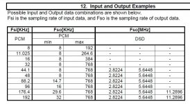
Everything is correct except that AK4137 can not convert 44.1 PCM to DSD 11.2. This can be done for PCM 176.4 and higher. PCM44.1 can be converted by AK4137 to max DSD 5.64, right?
Attachments
Everything is correct except that AK4137 can not convert 44.1 PCM to DSD 11.2. This can be done for PCM 176.4 and higher. PCM44.1 can be converted by AK4137 to max DSD 5.64, right?
Interesting point you raise. That table is in the example section of the AK4137 data sheet. However, I have input 16/44 PCM and measured the DSD output clock at 11.2MHz in that case. I will have to look into it some more later. Right now the dac test setup is down for some modding work.
Also, sorry for all the edits I have been doing to this post. Its very early in the morning here. 😕
Last edited:
The way the DSD output sample rate is programmed in AK4137 is via one of the I2C bus registers. It can be set to 64, 128, or 256 output sample rates. DSD256 can be 11.2MHz or 12.28MHz depending on the MCLK frequency. The Chinese dac boards both use 22.5MHz clocks for DSD conversion (except the the low clock frequency version of the low cost board), which would make DSD256 come out at 11.2MHz.
Also, for 16/44, BCLK should be around 1.4MHz = 2-channels * 16-bits * 44.1kHz.
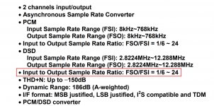
According to the blurb below in the AK4137 data sheet, for DSD output mode FSO/FSI can't exceed about 24. Well, 24 * 1.4MHz is easily more than 11.2MHz, so 16/44 would presumably be in the range that can be upsampled to DSD256.
That is the only interpretation of the data sheet I can think of at the moment that would explain why 11.2MHz DSD comes out when 16/44 goes into AK4137.
Also, for 16/44, BCLK should be around 1.4MHz = 2-channels * 16-bits * 44.1kHz.
According to the blurb below in the AK4137 data sheet, for DSD output mode FSO/FSI can't exceed about 24. Well, 24 * 1.4MHz is easily more than 11.2MHz, so 16/44 would presumably be in the range that can be upsampled to DSD256.
That is the only interpretation of the data sheet I can think of at the moment that would explain why 11.2MHz DSD comes out when 16/44 goes into AK4137.
Attachments
Last edited:
Ok, please check this out. I was sure of this (I'm not now), because the Chinese sellers on ebay and aliexpress mention this in a somewhat strange way:
"Note: When the input PCM signal is lower than 44.1K, it cannot be converted to DSD, nor can it be converted to a higher sampling rate of PCM. When the input PCM signal is lower than 176.4K, it can output DSD64. DSD128 can't output DSD256. " I think that the author had in mind: When the input PCM signal is lower than 176.4K, it can output DSD64 or DSD128 but can't output DSD256.
And "similar" information is here: 6moons audioreviews: Lindemann musicbook:15 dsd
"For a quick graphic representation of the various up/resampling options, we see, in CD mode though it's the same for USB file/streaming, native playback as 44.1-->44.1PCM; we see PCM44.1 rendered as DSD128, then maximally upsampled to DXD aka PCM352.8. In USB mode, we see an original PCM96 file rendered as DSD256; and finally the same 96 file first upsampled to 384 in PureMusic (replace with Audirvana, JRiver Media Center or similar), then rendered as DSD256 by the musicbook. By implication, any 128/256/320kbps MP3 streamed via Spotify & Co. can be upsampled to DXD or resampled to DSD128.
When the Lindemann is set to native, feeding it an already upsampled signal achieves otherwise missed target rates like 88.2/176.4kHz or 96/192kHz. When set to DSD, it renders Redbook files as DSD128. Upsampling those CD files to just 88.2kHz in player software then ups them to DSD256. If PCM upsampling is desired, the user decides whether to do it in 64-bit math with one of the many software players for Windows/Mac; on chip in the AK4137 SRC; or both. Physical discs obviously can't be pre-upsampled. They will always only render as DSD128, never as DSD256"
Last edited:
I definitely will take a bit more detailed look next time I have a chance. Won't be for at least a few days probably.
I did, however, do an experiment recently. I replaced the 22.5MHz clock with a 25MHz clock on one of the AK4137 boards to see if DSD conversion would still work at a slightly high and nonstandard sample rate. It did work, ES9038Q2M played the DSD output, and the DSD clock was measured at 12.5MHz. Nothing amiss, no muted or blanked output. As usual input source was a CD rip.
In the meantime, and before I can get back to subject of input and output sample rate limits, I have some other work to get finished up.
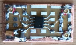
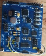
Returning for the time being to the jitter tests with a clock divider that I want to run, I have a few more pics showing how one of the AK4137 boards is being modded to allow external clocking. A LDVS to LVCMOS adapter board was constructed and attached to the back of one of the AK4137 boards. The output of the adapter replaces the output from a removed clock module. Power for the adapter board comes from the dedicated clock power regulator.
Attachments
- Home
- Source & Line
- Digital Line Level
- ES9038Q2M Board