I am selling this 2.5 months old DAC at $38 off to fund my next DIY project. Please, check the SWAP MEET for my post. I got it originally from MINISHOW.This is not a review and there is not much mod. Just the first impression of an inexpensive DAC using the ES9038Q2M.
The DAC links the TV cable box and a Sony BDP-7200 Blu-Ray player to a Harman Kardon AP2500 preamplifier. The Blu-Ray player also serves as my CD player.
View attachment 689897 View attachment 689898 View attachment 689899
The DAC is built around the VR1.07 of the ES9038Q2M board we discuss on this thread. At the beginning, I used a switching PS from the Topping VX-1. It sounds very good from the get go. The sound is open and transparent. It has a stable sound stage with good depth. The construction of the DAC box is well executed. A lot of hot glue to hold down the TFT display panel and wires. I like the upgraded RCA socket, better than the one on the original board.
View attachment 689906 View attachment 689907
I built a linear power supply for it. It can output 9 to 15 volts up to 1 ampere. It has a good size toroidal transformer and the board has a DC voltage panel for easy setting.
View attachment 689902
I was planning to install a dual voltage PS. But there is not enough room inside to house the transformer and PS board. I went the easy route.
I did not even try to add I/V. I just replace the output stage opamp with a LME89720. The board came with NE5532DD which should be very good. I changed the opamp only because I have a whole bunch of the 720 in my spare box.
View attachment 689903 View attachment 689904
I purchase an Apple Remote which allows me to perform all the front panel functions.
View attachment 689908
My previous DAC were a Rotel RSP-1570 (for main audio) and a Tianyun Zero DAC (computer sound). Both were 10 years old vintage. It is not surprising that the MShow DAC sounds pretty decent to me. The TFT display and remote function are nice bonus. I will not hesitate to recommend this as good investment for the money, at half the price of name brand DAC. In fact, later this month, I will try to sell mine to finance my ES9028PRO project.
NEW ES9038 ES9038Q2M DAC HIFI Decoder AUDIO IIS DSD DOP 384KHz + Amanero USB | eBay
Well, a quick and easy full AVCC schematic could be like the one attached below. However, some of the lines are very thin so it may display most clearly using Adobe Reader.
Can't believe that AVCC schematic has been downloaded 42 times already. It is as lousy a schematic as I can think of. Do people feel burned after looking at it, or is people's understanding of what is needed for AVCC so unclear that there is more of a need for a proper one?
By the way, besides making one that is easier to read, a better schematic should not assume use of either two single opamps or one dual, it should work equally well with either approach. It should also show that both AVCC supplies could share a common input filter.
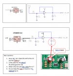
Hello Mark
I have a few questions can you take a look at the picture
Thanks
Serge
Attachments
In addition to my question about the AVCC schematic, is my belief that people should be willing to just give a try to making a layout drawing unreasonable?
Maybe I misunderstand people to be more advanced in what they understand about electronics than they really are?
It could be. It has been a long time since I was first starting out.
Maybe I misunderstand people to be more advanced in what they understand about electronics than they really are?
It could be. It has been a long time since I was first starting out.
Hello Mark
I have a few questions can you take a look at the picture
Thanks
Serge
1. V+ should probably be different. I am running all opamps on +-15 volts. +15 and ground might be okay for an AVCC opamp, but I am not sure about going lower given some issues I have seen with sound quality that I do not yet fully understand. I wonder if the opamp can charge up the output cap fast enough if it does not have enough Vcc available. After all, it can only lower its own output stage impedance between Vcc and the load.
The other issue is that +15v is too much for LTC6655. Please use a voltage that is okay with the LTC6655 data sheet, probably in the range from +5v to +12v.
2. See answer to question #1.
3. Min and max value of C2 according to ESS is 10uf to 47uf. Please read their notes from that I posted or from their downloads page: http://www.esstech.com/files/4514/4095/4306/Application_Note_Component_Selection_and_PCB_Layout.pdf
4. I use the cap on the board to act as C2 because it is very close to the dac pins.
Also, you didn't ask, but
5. There can be only one LTC6655 to be shared by both AVCC channel opamps, but there must be two AVCC opamps, one is needed for each channel. You can however share one R4 and C1 filter for both opamps. Otherwise the stereo sound imaging will not be good. Your schematic makes it look like only having one AVCC opamp is okay, it is *not* okay or stereo quality will suffer.
If you look at the picture of my first dac board, you may notice there is only one filter consisting of R4 and C1. But there is an LME49720 dual opamp, so there is one opamp for each channel, and one AVCC/2 Vref divider for each channel.
Last edited:
1. V+ should probably be different. I am running all opamps on +-15 volts. +15 and ground might be okay for an AVCC opamp, but I am not sure about going lower given some issues I have seen with sound quality that I do not yet fully understand. I wonder if the opamp can charge up the output cap fast enough if it does not have enough Vcc available. After all, it can only lower its own output stage impedance between Vcc and the load.
The other issue is that +15v is too much for LTC6655. Please use a voltage that is okay with the LTC6655 data sheet, probably in the range from +5v to +12v.
2. See answer to question #1.
3. Min and max value of C2 according to ESS is 10uf to 47uf. Please read their notes from that I posted or from their downloads page: http://www.esstech.com/files/4514/4095/4306/Application_Note_Component_Selection_and_PCB_Layout.pdf
4. I use the cap on the board to act as C2 because it is very close to the dac pins.
Also, you didn't ask, but
5. There can be only one LTC6655 to be shared by both AVCC channel opamps, but there must be two AVCC opamps, one is needed for each channel. You can also share one R4 and C1 filter for both opamps. Otherwise the stereo sound imaging will not be good. Your schematic makes it look like only having one AVCC opamp is okay, it is *not* okay or stereo quality will suffer.
Thanks Mark
maybe other people have to try with voltages <+ 12v and good results 😉
Serge
Thanks Mark
maybe other people have to try with voltages <+ 12v and good results 😉
Serge
How will they know if they use <+12 for the opamps if they have good results or not? They can only know if they compare by trying +15v too.
How will they know if they use <+12 for the opamps if they have good results or not? They can only know if they compare by trying +15v too.
And why +15v is the best solution 🙂
I told you, didn't I? I found that reducing impedance back to the power supply for my AVCC opamps improved bass. What does that mean? Bass discharges C2, and the opamp need to quickly charge it back up as soon as the voltage starts to drop. But, the opamp output stage is in some ways like a variable resistor. When more current is needed to charge C2 the opamps lowers the output stage resistance allowing more current to flow from +15v to C2. If a little bit of resistance in the wiring can reduce sound quality during that process, so can too little +v. Both small resistance and sufficient +v are needed to charge C2. I am using as little resistance as I can with two very short wires back to 1,000uf filter caps. So, I better keep +15v right where it is and not lower it. If anything I might want to raise it to +17v or +18v.
Okay, I just gave you an unproven theory based on what I observed. I am not equipped to measure anything so I can't be sure. I could do experiments to find out but no time for that. I am retired and this is not my job. What I know works, I told you. That is about the best advice I can give, if you do it that way, it works. If you do it another way it very well might not work so well. Don't know.
Okay, I just gave you an unproven theory based on what I observed. I am not equipped to measure anything so I can't be sure. I could do experiments to find out but no time for that. I am retired and this is not my job. What I know works, I told you. That is about the best advice I can give, if you do it that way, it works. If you do it another way it very well might not work so well. Don't know.
Last edited:
I told you, didn't I? I found that reducing impedance back to the power supply for my AVCC opamps improved bass. What does that mean? Bass discharges C2, and the opamp need to quickly charge it back up as soon as the voltage starts to drop. But, the opamp output stage is in some ways like a variable resistor. When more current is needed to charge C2 the opamps lowers the output stage resistance allowing more current to flow from +15v to C2. If a little bit of resistance in the wiring can reduce sound quality during that process, so can too little +v. Both small resistance and sufficient +v are needed to charge C2. I am using as little resistance as I can with two very short wires back to 1,000uf filter caps. So, I better keep +15v right where it is and not lower it. If anything I might want to raise it to +17v or +18v.
Ok 🙂 this is a good answer .
here the op amp works as a comparator, so it should be fine with Vcc from the input. at least I am running all series regulators in this fashion.
btw, now the AVCC circuit appears pretty much like a series reg: Vref-RCfilter-comparator.
I would ask why you need such an advanced Vref? Perhaps a TL431 would be good enough if followed by RCfilter? Of course, more current is required, so a pass transistor can be added and voltage divider in the feedback. It is important is to keep reverse currents away from the reg, so, another RC at the end. All this will result in low impedance, which more importantly will be virtually constant over a wide frequency range.
I mean something like this, just a bit more filtering: Series regulator using op-amp | Electronics Tutorial
Last edited:
eziitis,
Why such as advanced power supply? Noise voltage on AVCC intermodulates with the audio signal. For the dac to get -120dB distortion, the AVCC power supply needs to be as perfect as you can get it. A TL431 doesn't have good enough noise performance. Maybe you could filter with several pole filter and clean it up, don't know. It needs to have noise down as low as you can get it, -140dB noise would be great. That way it is a little below your other noise and distortion sources. Now, it could be that TLC6655 is somewhat better than you need for this in most cases, but some people are very picky about small distortion an so want a really good dac. They tried and abandoned things like LT3042 probably because of the noise at low audio frequencies, which cause both noise and distortion at the audio output of the dac due to intermodulation effects. The LT3042 or LT3045 data sheet shows an application circuit for reducing noise in the low audio band, it uses an LT6655 reference and the LT3042 or LT3045 as an output buffer. Maybe you could use that instead of this, one per channel. But, we are using opamps because we know they have been studied and they work for this particular dac chip.
Part of the problem we always have here is we are trying to build a good one-off dac without expensive test equipment and so sometimes we are better off just to do things we know or are pretty sure will work, even if they might be a little better than the minimum that could work if only we could measure and be sure. In this case it is cheaper by for me to use an LTC6655 than it is to buy an AP distortion analyzer and see if I could use a TL431 with a lot of filtering and get the numbers down where I want. If I could afford an AP, then I could compare the cost and performance of the two reference options. Could be will all the filter parts I would need there would be no savings at all. I would need a bigger PCB etc., worse MTBF due to more parts that can fail, etc. Trying to be cheap isn't always cheaper, even if you know for a fact you can hit the numbers with your AP analyzer.
Last edited:
Markw4,
I would not say it is advanced at all, just a power transistor, a couple of caps and resistors more. I also would not say that an application note from the chip producer for the demo board is a final truth, it rather gives some guidelines to follow. I recall, a while ago we were talking about MDAC schematics for AVCC, which indeed utilized pretty advanced reg for this.
TL431 as a reference is not so good as suggested one of course, but would it matter so much when having RC filter with about 1.6Hz cutoff frequency next to it?
personally, I believe opamp buffers like this are perfectly fine for a pretty little current draw and relatively steady loads. here might be different though. anyway, all this is rather an assumption without real measurements at the moment. just as I mentioned earlier a serial reg gave clearly richer sound than opamp buffer, at least in my implementation.
... It needs to have noise down as low as you can get it, -140dB noise would be great. That way it is a little below your other noise and distortion sources. Now, it could be that TLC6655 is somewhat better than you need for this in most cases ... ...
a while ago there was a comparison of ADM7150 and a series reg elsewhere (a personal communication). both of them were good at constant load. when a low power electric motor was connected as a load, a series reg remained stable, while ADM7150 measured some 20dB worse for the frequencies below 1kHz.
to me it sounds that LDO unless supported by the additional circuitry is not good enough for the oscillating load. but then we basically end up to use it just as Vref.
so, perhaps choosing some good voltage reference (ADR series for instance) and building a series reg from very beginning make some sense.
Hi eziitis,
Regarding all this AVCC power supply stuff, I guess I'm not sure where you are trying to go with this? It seems like you are not convinced that we need to make AVCC supplies the way we do, or that it should not matter how perfect they are, or that there should be more than one way to make one that is good enough, etc.
I will say that my recommendations to the group are based on a variety of factors, but probably the most important are the listening tests where my modded dac is compared with Benchmark DAC-3, and sometimes with Allo Katana.
Last time I did such testing I found that the changes I made to AVCC including adding an LTC6655 improved the sound quality enough to put my modded dac somewhere in between DAC-3 and Katana 1.1. So, I think that is pretty good. Already we are starting to hear that Katana 1.1 has been favorably compared to much more expensive dacs.
Since going to LTC6655 and rearranging the power wiring to AVCC supply improved the sound, I know it works better than the previous approach which at the time I though should be plenty good enough.
I have to wonder if what you are finding as good enough is not the same as my good enough. So long as I can keep improving the sound quality, that is what I will recommend. I can't see saying I will make my dac better and better as determined by careful listening tests, but I will tell everybody else they don't need theirs to be that good. No. That won't work for me. I have to recommend how to make the best sounding dac I know how.
Right now, the way I know how to make the best sounding dac requires the use of the AVCC supply that I recommend. That's all. If people want to use other approaches that is okay with me, I'm just trying to help people who want to make the best dac they can starting with a cheap ES9038Q2M board and modding from there.
EDIT: Regarding your description of 'richer sound' I have to wonder what that means in terms of distortion? I would not describe DAC- 3 that I try to work towards the sound of as being 'rich.' I would describe it as accurate, musical, true to the record, with a minimum (but not perfectly zero) of adding its own effects to the sound. I kind of suspect that 'rich' means a subtle type of distortion that is perceived as euphonic to your perceptions and or preferences. If so, that would be perfectly fine of course. Good for you to have what you like best. Maybe not the same as what I like, not sure. Haven't heard yours, but would like to someday. However, can't build too many of these to compare all the variations myself. I have a target sound and DAC-3 is it.
It has a sound that is consistent with state of the art measurements: Benchmark DAC3 HGC D/A preamplifier-headphone amplifier Measurements | Stereophile.com
I would say the sound quality descriptions in the following review are about correct for that sound I am going for: Benchmark DAC3 HGC review: An outstanding all-in-one headphone amp, DAC, and preamp | TechHive
It is accurate, yet musical, but not 'rich.' Don't know what else to say.
Last edited:
Page 6 of the LME49720 data sheet and a few pages onward will open some ideas of the importance of headroom. Next look at the open loop gain specs...that is a peek into why this chosen op amp is more a great voltage device rather than current. It appears bounded by architecture.
It's been mentioned that specs are meant to sway, but one needs to look inside the specs to get an idea of the where this op amp fits.
Now go look at the AD797 data sheet. Figure 13. Look at the headroom effects again on this op amp.
Now if we say that we want something that hammers down the design because we are unable to test and optimize then there is one great solution. Look at the spec sheet for the LME49600 Fig 31. The buffer will mitigate the effects the effects distortion due to op amp loading. Just configure it for unity gain. It ain't a cheap solution though.
Otherwise maybe a simple output small power transistor driven by the LME49720 might be a shot as well. Or just use an OPA1622 which will easily drive the mobile 38q2m. This someone should try as these are available on DIP adapters.
Try reading ES9311Q Datasheet. Has a lot of good features in one package.
LME49600 makes a great headphone amp, as I keep saying. Problem is that LME49720 uses most of its gain to linearize the LME49600 buffer. Output distortion of the combination is typically compromised as compared to LME49720 alone. If more current were needed than LME49720 alone could supply, don't know that the combination would beat ES9311Q for an AVCC supply, especially since it was designed for this exact task.
LME49600 makes a great headphone amp, as I keep saying. Problem is that LME49720 uses most of its gain to linearize the LME49600 buffer. Output distortion of the combination is typically compromised as compared to LME49720 alone. If more current were needed than LME49720 alone could supply, don't know that the combination would beat ES9311Q for an AVCC supply, especially since it was designed for this exact task.
Last edited:
Try using a 9311Q for through-hole leaded beginners? Availability? Hmmmmmm..... Compromise time. Realistic engineering need to come to terms with the situation.
Try reading the first sentence of the data sheet on page 9 of the LME49600 when combined with the LME49710/20. Distortion issues? Are we reading the same page? Then forward to page 31. Again it is not a cheap solution for AVCC. "The
vanishingly
low
residual
distortion
produced
by
LME49710/LME49600
is
below
the
capabilities
of
all
commercially
available
equipment."
Copy paste output from data sheet.
The distortion is not below the capabilities of all commercially made equipment today. Have you ever used LME49600? I have. Why don't you build one of the headphone amps I recommend and see how you like the sound? Then you can even try your HPA for an AVCC supply with your dac. Please let us know how you like it.
I will say I agree you are quite right it would be an expensive AVCC supply. Maybe $30 - $50 more than you really need to spend. Plus a lot more fabrication work.
I will say I agree you are quite right it would be an expensive AVCC supply. Maybe $30 - $50 more than you really need to spend. Plus a lot more fabrication work.
Last edited:
I have a LME49600 with the LME49710HA (round metal can) headphone amp.
I don't like headphones, never really like the closed in feel.
To me, I do it based on what I eventually listen to which is full range speakers with a pair of subs to really reach low. Cans on the head just does not have the same impact as whole body feel. Never will either.
I don't like headphones, never really like the closed in feel.
To me, I do it based on what I eventually listen to which is full range speakers with a pair of subs to really reach low. Cans on the head just does not have the same impact as whole body feel. Never will either.
Last edited:
- Home
- Source & Line
- Digital Line Level
- ES9038Q2M Board