Either something is drawing a lot of current or the regulator is bad, it sound like.
Does anything on the board feel warm to the touch? Sometimes filter caps can short. About the only thing that loads the 5v supply is the 3.3 volt regulator.
The difficulty with troubleshooting what might be a bad regulator or what might be a short somewhere is that you typically need to cut traces or remove components to figure out the problem.
You could also try turning off the power a measuring for a short to ground at the output of the 5v regulator. If you do find a low resistance to ground you could start by lifting the output pin of the regulator or cutting it and seeing if that changes anything. The short could be inside the regulator or outside of it.
If you don't find any low resistance to ground at the output of the 5v regulator that could mean the regulator is bad, or that it takes more voltage that a multimeter puts out to cause high current draw.
if you have another 5v power supply you could lift the output pin of the regulator and use another 5v power supply to power up the 5v bus and see if it comes back to life.
Also, maybe good to know that the 5v regulator only feeds the 3.3v regulator and the 5v power hole/pin at the I2C terminals.
Probably the preferred approach would be to try measuring for low resistance loading first and if nothing found then substitute another 5v supply. If you have a higher current 5v supply that might heat up anything causing a short or heavy load on the 5v but, or it might cause something to open like of fuse. If you proceed carefully chances are good you can fix it okay.
Just remember if you lift the 5v regulator output and apply +15 power to the board then the regulator might oscillate without an output capacitor hooked up to it. For that reason cutting a trace after the output capacitor might be a better place to interrupt the circuit.
Also, it should be possible to hook up another 5v supply without turning on the +15v power. In that case the +-15v would only be needed by the opamp which won't be hurt if the 5v is on. Or you could pull it from the socket.
EDIT: it could be andora76 suggestion is good too, although sometimes you can see a regulator that fails only with more loading than 10k. So, you might have to come back and look at that again if you don't find anything else. There is more than one way to start troubleshooting something like this.
I just check the other side of the board and it looks like that there was much heat at the 7805 place. So I guess that it is damaged for good.
I'll made measurements tomorrow.
Attachments
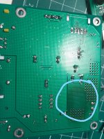
I just check the other side of the board and it looks like that there was much heat at the 7805 place.
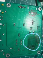
Looks like there is solder on the bottom of your board where the 5v could potentially get shorted. You should probably clean that solder up with some solder wick to help prevent any problems. I have circled some suspect areas in red below. Also, don't know why you would need to have the 5v PCM/I2S terminal soldered for anything.
In addition, looks like you could benefit from some more practice or instruction in soldering. If you know anyone good at it you might ask them for a lesson. Or, maybe youtube could help.
Attachments
Last edited:
Also, don't know why you would need to have the 5v PCM/I2S terminal soldered for anything.
In addition, looks like you could benefit from some more practice or instruction in soldering. If you know anyone good at it you might ask them for a lesson. Or, maybe youtube could help.
Few months ago I tried to connect a oled screen to the board.
@terry22, If you don't have any solder wick, I like to use Chem-wik brand. Also, you can buy small diameter 60/40 or even 63/37 leaded solder which is easy to solder with. It melts at a lower temperature than what they use to make most circuit boards, so you might need to use more heat when using it in combination with existing solder to get it all to melt. But, the hotter the temperature, the faster the flux burns off then the solder oxidizes and is ruined. At that point it needs to be removed and replaced. Usually you have to add new solder to be able to get it into a flowing liquid state so it can be wicked up. You have move fast sometimes if using high heat. Also, make sure solder is clean before you use it. You can wipe a strand of it with a paper towel until dark stuff mostly stops coming off of it. Those are oxides that have formed. You don't want those there when you heat it to solder. Lots of things to learn an experienced tech could show you.
EDIT: Something that can also be good to do is practice rolling the solder iron between your thumb and fingers without moving the tip in space. You just want it to rotate. Why? Sometimes when heating a joint if solder touches the solder iron tip it will tend to flow towards where the tip is hottest. That would be the side of the tip opposite the side you are using to heat the joint. A blob of solder on the the wrong side of the tip can make a mess or you might have to stop and clean it off. You can turn a problem into a solution by quickly rolling the tip between thumb and fingers to bring the hot side of the tip with solder around and into contact with the joint. You just have to do it quickly before the flux burns off. Practice may be needed, but it can make difficult solder situations much easier.
Also, when using solder wick, it works best if the side of the tip is laid flat against the solder wick. Only use the tip to heat solder wick if not room to use the flat side.
Regarding solder diameter for circuit boards I usually use 0.6mm and 0.3mm the most. Maybe 0.8mm for heavier stuff. You want to be able to feed in a controlled amount in a fairly short time. If a joint is small and will only need a little solder using fat diameter solder makes it very difficult to control how much solder gets fed in. If a lot of solder is needed for a big joint, very thin solder takes too long and too much motion to feed in. For cleaning tips, I usually use 0.8mm to flood the tip quickly with clean solder and active flux. Also, good to use one of the brillo pad type tip cleaners. Keep it clean and replace the pads when they don't clean up well.
Last edited:
The new clock will have to go where the old clock is. That means the old clock will have to come out. No hurry on that. Best to get some practice on easier things first.
Yes. it is not easy to remove.
I ordered some Chipquik Smd to help.
I have an old dac board (which is out of service) to train myself
Actually, when I removed the clock on my board it came out very easily using ChipQuik. One of the hardest things was trimming some of the top ground plane area around the clock solder pads with an Exacto knife. That is something that might really be worth practicing on an old board. Important to use a fresh, sharp, very pointy blade in the knife. A dull blade makes mistakes more likely. After cutting around the periphery of a piece you want to remove, then get under the corner of it with the tip of the knife and lift it up a little. Once a you get a little bit lifted a pliers or forceps type of tool can be used to gently peel it back. 'Non-locking ophthalmic needle holders' work well too, the foil can be rolled around it like opening a sardine can. I use the little needle holders for lots of things. They are good for bending and positioning component leads and small wires, for one type of example, and stronger than tweezers.
The reason for doing that was the that the clock solder pads on the board are just about exactly the right size, but no extra room for error at all. Trimming away a bit a ground plane leaves a little clearance around the pads to solder in the new clock. Very important to get new clock exactly in position and not let it move while soldering. I have various ways of holding things in place while I solder. Sometimes GafFer tape is good. Sometimes a spring loaded holder, it just depends. Someone to provide a 3rd hand could help hold the clock. The board could be taped down or held in a vice. It is probably worth spending sufficient time on positioning and holding. That way soldering goes fast and easy, and much more likely with no problems occurring.
There is also some two-part epoxy stuff for repairing solder mask on boards which can be very useful sometimes if the solder mask gets scratched. Solder mask is of course the (usually) green color coating on circuit boards that keeps solder from sticking where you don't want it to.
The professional micro-soldering guys sometimes use the epoxy to repair solder mask which is where I heard about it. It is called "Chemtronics CW2500 Circuitworks Epoxy Overcoat" and it is available from electronics suppliers and places like amazon.com. Best to let it cure overnight, although a heat gun can speed it up some.
Last edited:
I know people have used nail polish to do the same mask repair job. Not suggesting it is a good idea, but in a pinch, if you don't have access to much else, it apparently does work.
a little improvement after soldering a 10uf wima for the clock.
[img=https://abload.de/thumb/20180724_194301iych9.jpg]
[img=https://abload.de/thumb/es9038q2mplatinewimas8fob.jpg]
with this soldering points the Sound improve.
[img=https://abload.de/thumb/20180724_194301iych9.jpg]
[img=https://abload.de/thumb/es9038q2mplatinewimas8fob.jpg]
with this soldering points the Sound improve.
Last edited:
@system54, I will post your pics below so they can remain part of the thread over time. It looks like the 10uf you added close to the clock will also affect the entire 3.3v rail, including things like AVCC. Whatever difference you hear is probably due to cleaner 3.3v power for multiple things, not just for the clock.
Attachments
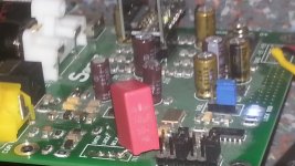
i had the wima soldered behind the ferrite bead bevor and it was not better.
the gnd was at the Tantal gnd obviously that was not good
the gnd was at the Tantal gnd obviously that was not good
Last edited:
In the picture you posted the cap is on the side of the inductor that would be more likely to help all of the 3.3v bus. AVCC is the most sensitive thing on that bus, and putting more caps just at the AVCC cap pins would probably do the most good.
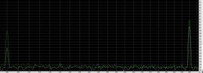
THD measurement @1Khz -3dbfs
Hi,
I've done measurement with a xmos usb to spdif ( isolated, 24 bit 96Khz ) and Asus xonar soundcard ( using Rmaa) . You will find harmonics before and after the avcc mod ( aop lme49720na). the difference on C3 is about -7db and -18db for C2 , not to bad. The board has a lm317 supply, it's much better than a wallmart ...
I've also tested few aop swap for the buffer stage ,no difference in measure ( stock NE5532, LME49720na) .
I've also tried a muses 8920, the C2 harmonic has disapeared on the left channel !!! but the C3 was unchanged.
Attachments
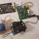
occip, Please post pictures of your test setup including AVCC supply and buffers. Hard to be sure what exactly you are testing including layout, etc., otherwise. Thanks!
Last edited:
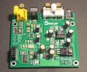
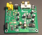
That is not a SPDIF LDO. It is an inverting buffer used as an amplifier to condition the SPDIF signal. Please do not change it.
Wow, $35 is a good price for all that! Thank you for the picture, too.
Of course, you probably know what I am going to say because I want our other potential modder's to do very nice, very careful work. Have to say I notice the AVCC supply you show in the picture could be laid out a little more clean, with shorter wires, preferably on the other side of the ground plane where it would be better shielded, and so on.
With long wires hanging out in space and the opamp right next to the noisy digital microcontroller, there are a number of opportunities for performance problems to creep in. You don't worry about those things? I know I do for the board I have been working on here.
Also, what about the future of the board in the picture, any plans to do more work on it? Maybe clean up the AVCC supply, add an I/V output stage, etc. Since you have the board, may as well do a little more with it, wouldn't you agree? It will sound much better for sure.
Whatever you may decide to do next if anything at all, thanks again for letting us see what you have so far. I hope other people will let us see pictures of what they have been doing too. I don't want to scare people off that their work might get criticized a little, but at the same time we would like to encourage everybody to get the best sound quality possible which means layout is part of what has be considered too, not just the circuit schematic. Hope you are okay with that.
Last edited:
- Home
- Source & Line
- Digital Line Level
- ES9038Q2M Board