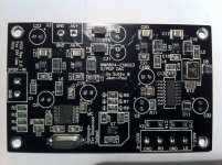
Finally I've received my ES9023 PCBs this afternoon, little boards : 80 x 50 mm only.
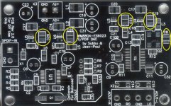
Dear Emeritus would you please point me the correct way to solder the polarized Tantalums caps ?
(C19, C22, C26, C29 and C8 for SE and C19, C22, C26 and C8 for BAL)
I've scanned the PCB and highlight concerned Tantalum caps footprint.
Thanks for your "enlighted" advices 😉
Dear Emeritus would you please point me the correct way to solder the polarized Tantalums caps ?
(C19, C22, C26, C29 and C8 for SE and C19, C22, C26 and C8 for BAL)
I've scanned the PCB and highlight concerned Tantalum caps footprint.
Thanks for your "enlighted" advices 😉
Attachments
That's correct. If you are in doubt, one small trick (that's what I did) - measure the pads to the ground, there should be continuity between ground and -ve pad.
C8 is after the inductor (L3), so it can be the same parts as in the BOM which is non-polarized. Regardless, the above trick will tell you the correct orientation quickly.
C8 is after the inductor (L3), so it can be the same parts as in the BOM which is non-polarized. Regardless, the above trick will tell you the correct orientation quickly.
C8 is after the inductor (L3), so it can be the same parts as in the BOM which is non-polarized.
Wrong, C8 was changed to a 4.7 µF 10 or 16 V tantalum cap as the regs don't like too low ESR caps at their outputs. Phil, you are right about the polarity. They are correct in the picture in post #122 but C8 is orientated the opposite way so + to the upper side. Normally I would have orientated all the same way but we started with non polarized caps in which case it would not have mattered.
Last edited:
Wrong, C8 was changed to a 4.7 µF 10 or 16 V tantalum cap as the regs don't like too low ESR caps at their outputs.
And the polarity for C8 is ?
Last edited:
Wrong, C8 was changed to a 4.7 µF 10 or 16 V tantalum cap as the regs don't like too low ESR caps at their outputs.
Yeah, but C8 is not right after the reg. It is C19 - L3 - C8. Are you saying L3 is not enough to decouple C8 from the reg? Anyway, I have no problem with using the 1uF film cap as in the BOM.
Edit: so the revised circuit is C19 (4.7uF tanlaum) -> L3 -> C8 (4.7uF tanlalum), i.e. C8 is changed from the 1uF film to 4.7uF tantalum.
Last edited:
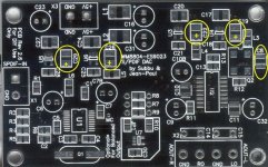
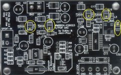
Phil, you are right about the polarity. They are correct in the picture in post #122 but C8 is orientated the opposite way so + to the upper side.
Great Jean-Paul, thanks.
BTW the attached pic should be correct.
GB members will receive C19-22-26-29-8 (SE) or C19-22-26-8 (BAL) Vishay/Sprague 4.7µF/10v Tantalum caps, according to ordered versions.
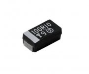
Second pic shows Tantalum SMD cap, white line indicates "+" polarity side.
Regards
Phil
Attachments

Last edited:
Yeah, but C8 is not right after the reg. It is C19 - L3 - C8. Are you saying L3 is not enough to decouple C8 from the reg? Anyway, I have no problem with using the 1uF film cap as in the BOM.
Edit: so the revised circuit is C19 (4.7uF tanlaum) -> L3 -> C8 (4.7uF tanlalum), i.e. C8 is changed from the 1uF film to 4.7uF tantalum.
Thanks for telling me what is in our design 😉 It was repeated a few times that 4.7 µF tantalum is better for C8. It is not a major difference but still. But as always YMMV, I invite you to try it out.
Edit: so the revised circuit is C19 (4.7uF tantalum) -> L3 -> C8 (4.7uF tantalum), i.e. C8 is changed from the 1uF film to 4.7uF tantalum.
Apart from the original spelling errors this is correct.
Last edited:
Great Jean-Paul, thanks.
BTW the attached pic should be correct.
GB members will receive C19-22-26-29-8 (SE) or C19-22-26-8 (BAL) Vishay/Sprague 4.7µF/10v Tantalum caps, according to ordered versions.
Second pic shows Tantalum SMD cap, white line indicates "+" polarity side.
Regards
Phil
Second pic shows Tantalum SMD cap, white line indicates "+" polarity side.
Please let everyone read this.
Attachments
Last edited:
I must first ship some parcels tomorrow ...
After yes, it is planned, with more pics to come.
I'll try to make the ES9023 working in I2S mode using this USB I/O :
http://www.diyaudio.com/forums/vendors-bazaar/216474-usb-i2s-384khz-dsd-converter.html
After yes, it is planned, with more pics to come.
I'll try to make the ES9023 working in I2S mode using this USB I/O :
http://www.diyaudio.com/forums/vendors-bazaar/216474-usb-i2s-384khz-dsd-converter.html
Last edited:
That's my second board is for - to use different components than the 1st and compare 🙂It is not a major difference but still. But as always YMMV, I invite you to try it out.
Please wait with soldering the caps. I just thought yours should be a special version considering all your effort with the power supply dilemma/group buy. Wait for the postman !
Mmm, I just read you will be using USB. Nearly made me change my thoughts.
Mmm, I just read you will be using USB. Nearly made me change my thoughts.
Last edited:
That's my second board is for - to use different components than the 1st and compare 🙂
Ah now we are talking. I am interested to read your findings. I finished one with BG 0.47 µF NX HiQ parallel with the 1 µF PPS for Vneg and i like that one a lot.
Hi All
As expected, I've received this morning last delivery (Tantalum), and packed all the parcels.
Today, I've sent those members parts :
APK - DiyYes - schuhbu - touchdown - mrwireless - Tome - gig - Ginum - danzup - Ciu - skouliki
Tracking will be available tomorrow, have a look a the GoogleDoc for the number.
I hope to be abble to ship remaining enveloppes tomorrow.
Regards
Phil
PS : sorry gig, I've missed your morning mail 🙁
Last edited:
Hi
End of shipping right now for remaining members :
rvravan - julius20 - Albundi - Raymondo - samoloko
veggiel - ryssen - grufti - simon123 - jacek_k_wawa
GoogleDoc spreadsheet has been updated.
Tracking will be available tomorrow.
Phil
End of shipping right now for remaining members :
rvravan - julius20 - Albundi - Raymondo - samoloko
veggiel - ryssen - grufti - simon123 - jacek_k_wawa
GoogleDoc spreadsheet has been updated.
Tracking will be available tomorrow.
Phil
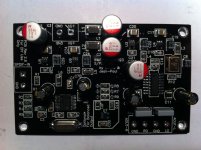
SMD parts populated.
Nothing special, be carefull with C8, must be soldered after Q2.
I've begun with ES9023, WM8804, MIC5205, 74LVC1, followed with 0805 resistors and caps, 1210 caps, inductors, crystal & oscillator, tantalum caps, film caps and electrolytics.
No solder bridge on WM8804 😉
C10 is very close to C10b, you need to bend a little C16 & C31.
That's all, firing on Monday in SE configuration.
Phil
Attachments
Last edited:
- Status
- Not open for further replies.
- Home
- Group Buys
- ES9023 / WM8804 S/PDIF DAC Parts GB EU Only