The notch is the top, pin 1 is top left on the PCB, i.e. the pin near C18 and R13.
The chip should be mounted with the "50 Mhz" letters on the edge side of the pcb, the ACV letters should be on the inner side of the pcb. Go back to a few page, Syklab has a picture that show the correct orientation of the OSC.
Good luck!!
The chip should be mounted with the "50 Mhz" letters on the edge side of the pcb, the ACV letters should be on the inner side of the pcb. Go back to a few page, Syklab has a picture that show the correct orientation of the OSC.
Good luck!!
This is why I like diyaudio! you guys are the best!!! Q2 was wrong.... I'm listening to Michael Hedges pumping thru my DV336se (modded) to my Sennheiser HD650. sounds great... cant wait till it breaks in!!
forgot... thanks syklab and pchw for all your help!
many thanks to Subbu and JP for giving us this DAC.
*back to listening to music*
forgot... thanks syklab and pchw for all your help!
many thanks to Subbu and JP for giving us this DAC.
*back to listening to music*
Last edited:
Congratulation, and my turn to seek help 🙂
I am getting no sound from my dac, but all voltages at the chip's
pins appeared to be on the spot. Any tip on how to test the WM and ESS
chip is dead or alive?
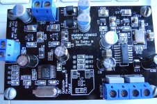
Attach a photo of the board to borrow another pair of eyes to see anything wrong.
TIA,
I am getting no sound from my dac, but all voltages at the chip's
pins appeared to be on the spot. Any tip on how to test the WM and ESS
chip is dead or alive?
Attach a photo of the board to borrow another pair of eyes to see anything wrong.
TIA,
Attachments
Hi TIA,
Are you measuring from the regulator output pin or from the pin 7 and pin 19 from 8804 and
pin 5 on 9023?
Are you measuring from the regulator output pin or from the pin 7 and pin 19 from 8804 and
pin 5 on 9023?
I checked from the 8804 and 9023 pins. I also followed the schematic to check the connectivities from each pin to the other components to make sure the pins are soldered solidly.
In the case of in need of replacing the 8804 and 9023, any suggested techniques to make this easier? This is my first solder my own smd project as well, so I can use all advise that I can get 🙂
In the case of in need of replacing the 8804 and 9023, any suggested techniques to make this easier? This is my first solder my own smd project as well, so I can use all advise that I can get 🙂
Has anyone tried using the twisted pear s/pdif transceiver's i2s output feeding to this DAC? I followed the silk screen for a balanced DAC minus JP2 and the components in the *optional section. But I dont get any output, I'm looking to test the board and make sure everything is kosher prior to adding the additional components.
And yes.. all the voltages at the regulators(IN/OUT) measure as expected, using my unbalanced version as reference.
thanks in advance
And yes.. all the voltages at the regulators(IN/OUT) measure as expected, using my unbalanced version as reference.
thanks in advance
did I miss the power supply group buy?
😱
I haven't been keeping up on this thread. Did I miss the power supply group buy?! I hope not. I really wanted 2 of the power supplies.
😱
I haven't been keeping up on this thread. Did I miss the power supply group buy?! I hope not. I really wanted 2 of the power supplies.
if someone needs two of these with the Sabre chips, I bought too many, and don't think I will get to this for sometime. So I will sell at cost I paid UNIXdeveloper for them. PM if interested.
I will take them.if someone needs two of these with the Sabre chips, I bought too many, and don't think I will get to this for sometime. So I will sell at cost I paid UNIXdeveloper for them. PM if interested.
RC
This was never meant to be a beginners project but I truly admire the strong will to conquer SMD parts for a first project ! I see some soldering tips are needed.
Guys/gals, please do the following if you want your DAC to also look good without overheating parts:
- good old 60/40 leaded quality solder thinner or equal to 0.75 mm. Fluitin is a good quality solder.
- use angled tweezers to place the parts straight and not skewed. You won't burn your fingers as a bonus.
- solder the parts at one side and correct when it is still possible by moving the tweezers and heating the part at the same time.
- solder the other side of the part.
- use desoldering braid to remove excess solder.
You can solder all pins on one side of WM8804 in one turn (yes with some or even all pins shorted by solder!) and then remove excess solder with desoldering braid (also in one turn). Heat up the soldering braid beforehand and when it is hot you can suck all excess solder nicely away while moving the braid quickly over the IC pins with the soldering iron.
And ... please do not forget to give an impression of the sound quality of the DAC.
Last edited:
Warning: I would like to advise to use tantalum or electrolytic 4.7 µF caps for C19, C22, C26 and C29, While I never used ceramic 4.7 µF 1210 caps at that spot I did this now and found the MIC5205 are not keen on ceramic caps at the outputs. At least some of them don't like the very low ESR of ceramic caps in this particular value. After checking the datasheet it is clear to me not to use ceramic caps there, at the input they are OK.
So please use 4.7 µF 10 V 1210 size tantalum or electrolytic caps for decoupling the outputs of the MIC5205 regs. Those of you that use ADP151 don't need to worry as those are designed to work with ceramic caps at their outputs.
I haven't experienced the problems with 1 µF ceramic caps at the outputs but I would like to advise to play safe. You could swap input (1 µF) and output caps (4.7 µF) but it would be better to order some tantalums.
Last edited:
Today, I reflow
1. WM8804
2. 12Mhz crystal (I don't think there is polarity, but I turn it around anyway).
3. 50Mhz OSC.
Hooked it up again, music started flowing!! I still don't know exactly what I did wrong or right 🙂
The PSU is composed of parts I have on hand:
1. 9-0-9 transformer =>
2. full wave into 4700uF =>
3. a cap multiplier =>
4. 2200uF => MC7805 => 2200uF
Thanks JP and Subbu!!
PS, I am using the ceramic 4.7uF in the BOM with the MIC, seems to be fine.
2200 µF after the reg without series resistor ?!? Way too large IMO but have it your way. Glad the DAC works. Crystals don't have polarity 😉
The ceramic caps after the MIC5205 sometimes will cause the MIC5205 to oscillate. These regs were not intended for use with ceramic caps at all at their outputs. The first time I used a ceramic 4.7 µF cap I had one MIC oscillating straight away. Till now I used either 1 µF 16 V PPS or tantalum 4.7 µF 10 V and in some cases 1 µF ceramic as I did not have other caps at hand. The optimal would be 2.2 till 4.7 µF PPS/tantalum/electrolytic.
The ceramic caps after the MIC5205 sometimes will cause the MIC5205 to oscillate. These regs were not intended for use with ceramic caps at all at their outputs. The first time I used a ceramic 4.7 µF cap I had one MIC oscillating straight away. Till now I used either 1 µF 16 V PPS or tantalum 4.7 µF 10 V and in some cases 1 µF ceramic as I did not have other caps at hand. The optimal would be 2.2 till 4.7 µF PPS/tantalum/electrolytic.
Last edited:
I built another DAC without the S/PDIF section, following the balanced guide, and this time I actually got sound when I fed it i2s from an unbalanced version. Like my previous problem and pchws' I suspect my OSC isnt soldered down properly I'll have to try and reflow another night.
Again.. JP and Subbu thanks!
p.s.
yea.. 60/40 does flow a lot easier than say Cardas tri-eutetic solder.. I wish I realized that before.
PSU:
twisted pears' LCDPS and Antek dual secondary 9V transformer
Again.. JP and Subbu thanks!
p.s.
yea.. 60/40 does flow a lot easier than say Cardas tri-eutetic solder.. I wish I realized that before.
PSU:
twisted pears' LCDPS and Antek dual secondary 9V transformer
Last edited:
"Cardas tri-eutectic solder" ?!?! What a name. The joints look as ugly as those made with standard leadfree solder complete with all its associated negative points. There is no substitute for quality leaded solder if you like good joints that last. I like to think green and that's why I still use 60/40 or 60/38/2. It is a shame many devices fail because of simple dry joints which is not good for the environment at all.
Last edited:
Warning: I would like to advise to use tantalum or electrolytic 4.7 µF caps for C19, C22, C26 and C29, While I never used ceramic 4.7 µF 1210 caps at that spot I did this now and found the MIC5205 are not keen on ceramic caps at the outputs. At least some of them don't like the very low ESR of ceramic caps in this particular value. After checking the datasheet it is clear to me not to use ceramic caps there, at the input they are OK.
So please use 4.7 µF 10 V 1210 size tantalum or electrolytic caps for decoupling the outputs of the MIC5205 regs. Those of you that use ADP151 don't need to worry as those are designed to work with ceramic caps at their outputs.
I haven't experienced the problems with 1 µF ceramic caps at the outputs but I would like to advise to play safe. You could swap input (1 µF) and output caps (4.7 µF) but it would be better to order some tantalums.
Like this one from the first revision of the BOM.
CAP TANT 4.7UF 16V 10% 1210
"Part not found".... but as long as it are the ones that were in the BOM earlier it is OK. Please note that I don't like to endorse the dirty business involved in tantalum/coltan mining but these caps are the better ones for this purpose. If you find alternatives that are not ultra low ESR you can use those as well.
Last edited:
I know that this GB has been closed. Is there a plan to run the new GB?
I have few question...
- is there point on the board where I could connect directly using I2S to the DAC? Thinking to try USB to I2S async converter as the alternative to the SPDI/F
- will this DAC compatible to the JG filter buffer, which originally created for ES9022?
I have few question...
- is there point on the board where I could connect directly using I2S to the DAC? Thinking to try USB to I2S async converter as the alternative to the SPDI/F
- will this DAC compatible to the JG filter buffer, which originally created for ES9022?
- Status
- Not open for further replies.
- Home
- Group Buys
- ES9023 / WM8804 S/PDIF DAC Group Buy