What do you connect to the rear mounted BNC connector ???
Kinda interested, have to think about it a little bit more.
Kinda interested, have to think about it a little bit more.
Hello jasse,
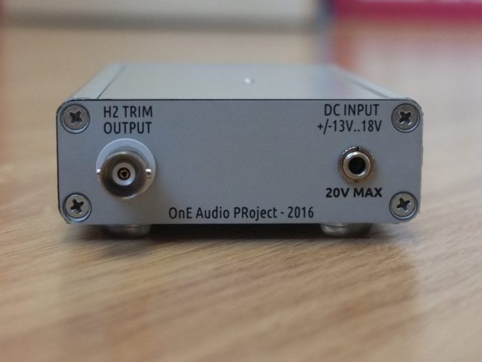
The BNC output on the rear panel is the H2 trimming output.
See the schematics (first post), this output can be used to trim the H2
level to minimum. In practice, without touching the trim,
the H2 level in nearly not measurable.
You can read also the AN67 that describe the adjustment procedure.
Regards.
Frex
Hello,
These days, i've made a printable silkscreen for the front and rear
panels of the oscillator. This allows a nice finish.
Some picture of the result :
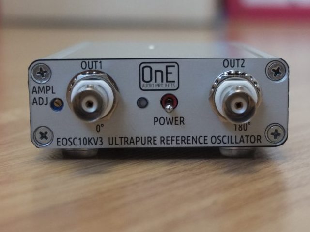
Front panel view
Rear panel view
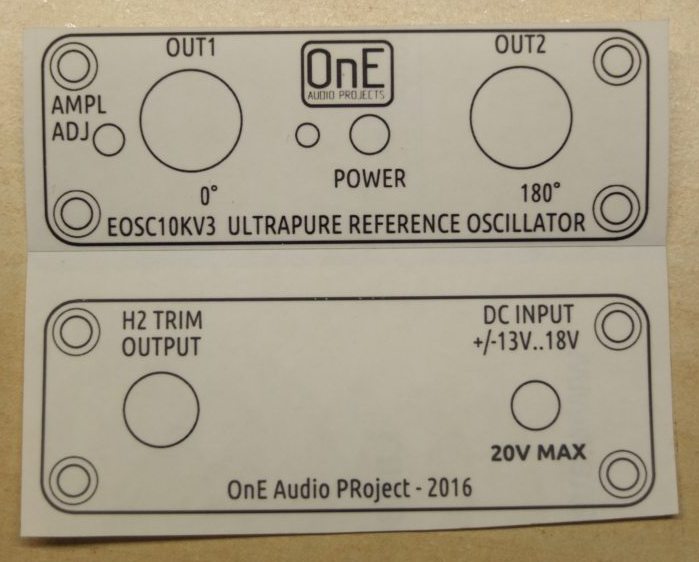
The panels stickers
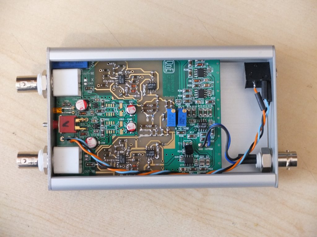
Inside top view
I will now provide these panels stickers for free to all
bare PCB buyers.
A complete unit will send next week to Samuel for extended
measurement.
Frex
These days, i've made a printable silkscreen for the front and rear
panels of the oscillator. This allows a nice finish.
Some picture of the result :
Front panel view
Rear panel view
The panels stickers
Inside top view
I will now provide these panels stickers for free to all
bare PCB buyers.
A complete unit will send next week to Samuel for extended
measurement.
Frex
Ok Richard.
I've done many measurements and i am very confident about their validity.
But of course, when we speak about some hundreds of nanovolts, we must take much care when interpreting ...
So, i have finished my first oscillators with it's enclosure (updated pictures on my first post).
and i am nearly ready to send the unit to Samuel.
I think he could make some serious measurements with it's high-end setup that i can only dream....
Frex
That will be a great thing to do. I only have AP 2722 and ShibaSoku 725D and Panasonic VP 7722A analyzers as basic tools (plus notch filters etc).
THx-RNMarsh
Richard-
I can verify the performance with the CLT-1. HD3 and up are -170 dB unloaded. If you get it and want to verify its performance.
I can verify the performance with the CLT-1. HD3 and up are -170 dB unloaded. If you get it and want to verify its performance.
Thanks Demian. But I am still in Asia for awhile. How does Victor's compare though? He has many freqs available also.
Let's wait until Samual's report.
-RNM
Let's wait until Samual's report.
-RNM
Last edited:
Q: Have you looked at the phase response of the notch at 2H to be sure the angle isnt subtracting from the true 2H level ??
THx-RNMarsh
What would be the mechanism of this effect?
I think I saw it too in connection with an old Bruel & Kjaer analyzer.
Thanks
Your notch filter has 10dB atten at 2F and 5dB at 3F. (2H and 3H).
Mag and phase of the notch will atten the harmonics by those amounts and thus you have to add it to the measured data.
THx-RNMarsh
Mag and phase of the notch will atten the harmonics by those amounts and thus you have to add it to the measured data.
THx-RNMarsh
Hello,
I've tried today to change the oscillator frequency to 1kHz.
Many DIYers asked me for doing that, and even for the previous versions i never tried. The good new is that seem to work very well.
I only changed the two RC networks to get 1/(PIxRxC).
I used only available parts on my bench; thick film resitors instead of thin film melf.
(The output amplitude regulation loop need to be slightly slowed down, to reduce a slow damping. For now, i use it as is).
I don't have (yet) a twinT notch filter for 1kHz to measure precisely the THD performance for this frequency.
So, i've made a direct measurement using my EADCAKMv1 ADC based on AK5394A.
With the output of the oscillator (set to 1V rms) connected directly to ADC input
i measure H3 level at -120 dBV, giving about 0.0001% THD.
This (very low) THD level come probably mainly from the ADC itself.
I will build a new notch box for 1kHz soon, in order to make more consistant measurements.
Although, i ask me if that could be a cool project to make a good PCB for a dual notch filter/amplifier with toggle/verify function ...I keep that in mind.
In a near future, i would build a 11kHz version to use it in conjunction with the 10kHz to make serious IMD measurements.
Frex
EOSC10KV3 1kHz version performance measurements
Hello all,
These days, i made some measurement on the EOSC10kV3 with 1kHz output frequency.
Finally, it was not difficult to change the oscillator frequency.
Only the two RC network changed to fit with 1kHz.
The time constant of the rectifier/integrator stage require to be larger to avoid
long damping time of the amplitude stabilization. For my first tests, i use it as is.
I tried first to make direct measurement with my ADC and i get (for 1Vrms out)
H2=-132dBV and H3= -120dBV (all others much lower).
These level come mainly from the ADC itself .
To make more deeper measurements, then i made a new "notch box" dedicated
to test the oscillator at this frequency. As for the 10kHz version, it include a 1kHz
Twin-T notch filter and a 40dB post-amplifier.
I added also inside a passive attenuator that can be switched in place of the Twin-T filter.
This passive attenuator is set at same attenuation as the Twin-T filter at
the fundamental frequency of the oscillator (here about - 62dB).
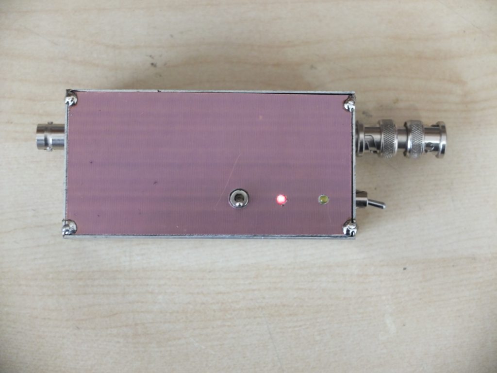
The notch box looks like that :
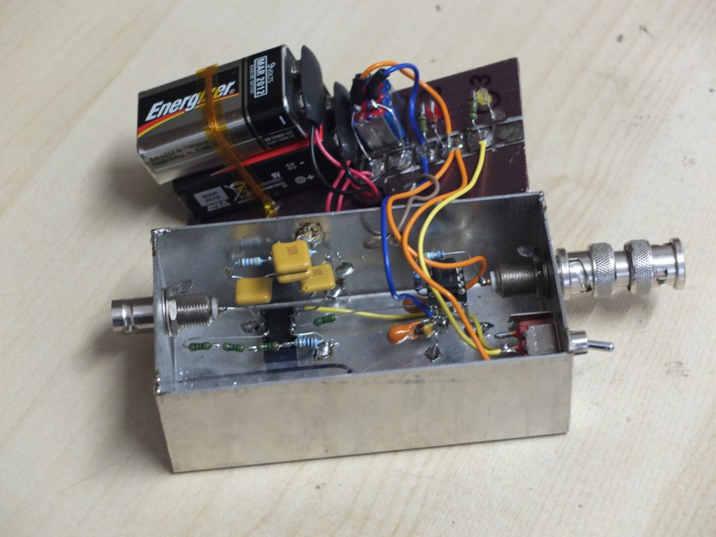
And inside it :
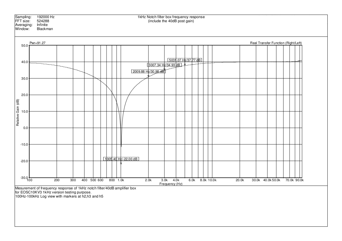
The notch box frequency response :
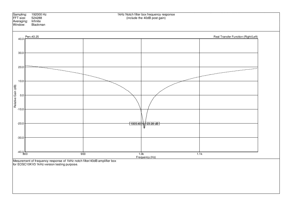
A zoomed view of maximum attenuation :
After the notch filter, the 40dB post-amplifier extract all small level signal,
and then i get at ADC input : 0dBV + (- 60dB) + (+40dB) = - 20dBV at the ADC input.
This level (far from full scale of the ADC) allow to measure harmonics level
with 40dB vertical offset. At this level, there is extremely low THD contribution of the ADC
and post amplifier. To verify that the 40dB post amplifier and ADC doesn't introduce THD themselves,
the notch box include in the signal chain a relay and the 60dB passive divider.
When you switch it, you must see spectrum without any harmonics because
fundamental AND harmonics are 60dB attenuated, so they must be flooded in noise.
Verify spectrum using passive attenuator :
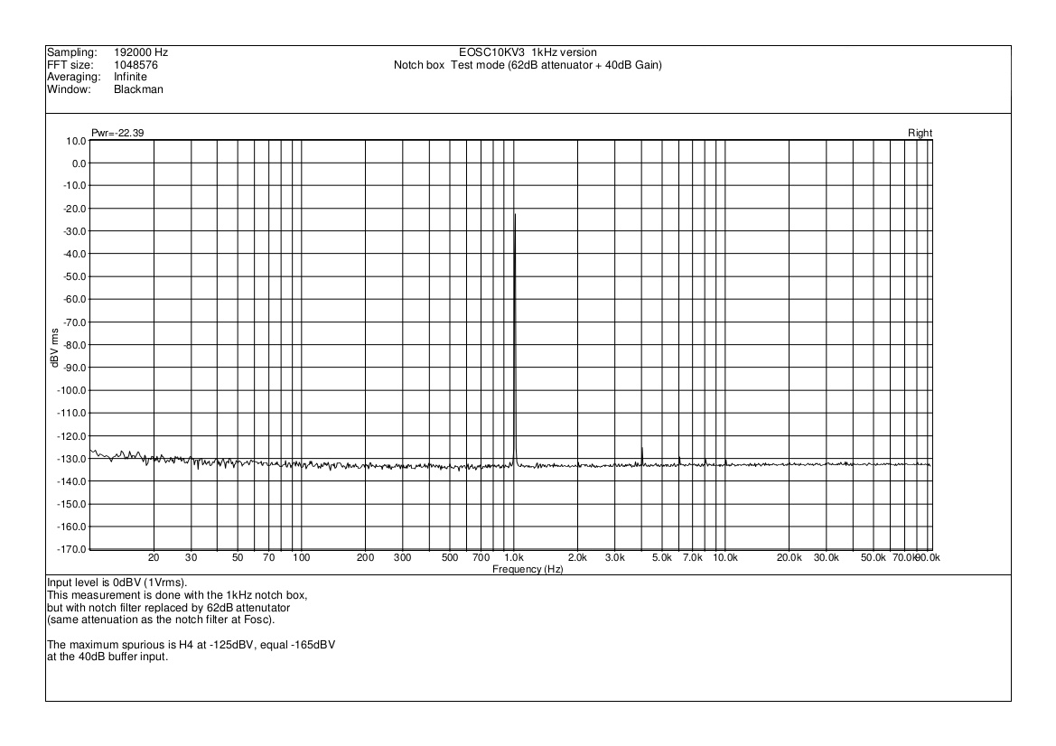
We can see on the spectrum above that there is only H5 content at -125 dBV
and noise floor less than -130dBV .
Because of the 100x gain (40dB), that give H5 level at -165 dB and noise floor
at -170dBV ! So, with this setup we are able to show very low harmonics level.
Now, we switch ON the Notch filter to measure THD of the EOSC10KV3 1kHz oscillator.
(Output Level set to 1Vrms = 0dBV).
Resulting THD spectrum of EOSC10KV3 1kHz version :
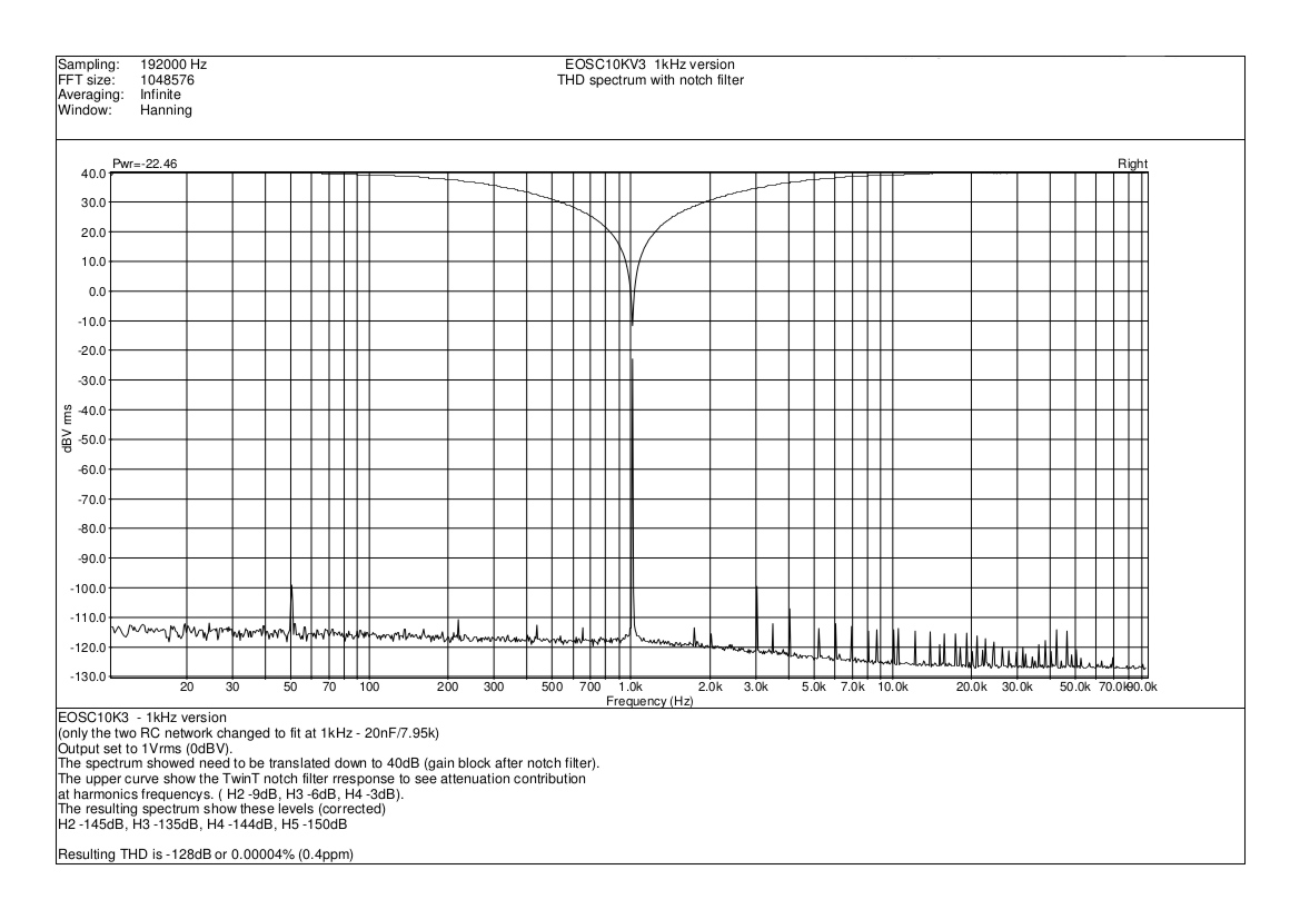
We can see now with the notch box, the THD with 40dB gain.
The spectrum showed need to be translated down to 40dB (gain block after notch filter).
The upper curve in spectrum above show the Twin-T notch filter response to see attenuation
contribution at harmonics frequencies ( H2 -9dB, H3 -6dB, H4 -3dB).
The resulting spectrum show these levels (corrected with 40dB gain ant notch attenuation) :
H2 -145dB, H3 -135dB, H4 -144dB, H5 -150dB
The resulting THD is - 128dB or 0.00004% (0.4ppm)
This result confirm the exceptional THD performance (much below ppm level) of the oscillator, even
at 1kHz and without change in design.
Bare PCB still available for interested DIYers...
Best regards.
Hello all,
These days, i made some measurement on the EOSC10kV3 with 1kHz output frequency.
Finally, it was not difficult to change the oscillator frequency.
Only the two RC network changed to fit with 1kHz.
The time constant of the rectifier/integrator stage require to be larger to avoid
long damping time of the amplitude stabilization. For my first tests, i use it as is.
I tried first to make direct measurement with my ADC and i get (for 1Vrms out)
H2=-132dBV and H3= -120dBV (all others much lower).
These level come mainly from the ADC itself .
To make more deeper measurements, then i made a new "notch box" dedicated
to test the oscillator at this frequency. As for the 10kHz version, it include a 1kHz
Twin-T notch filter and a 40dB post-amplifier.
I added also inside a passive attenuator that can be switched in place of the Twin-T filter.
This passive attenuator is set at same attenuation as the Twin-T filter at
the fundamental frequency of the oscillator (here about - 62dB).
The notch box looks like that :
And inside it :
The notch box frequency response :
A zoomed view of maximum attenuation :
After the notch filter, the 40dB post-amplifier extract all small level signal,
and then i get at ADC input : 0dBV + (- 60dB) + (+40dB) = - 20dBV at the ADC input.
This level (far from full scale of the ADC) allow to measure harmonics level
with 40dB vertical offset. At this level, there is extremely low THD contribution of the ADC
and post amplifier. To verify that the 40dB post amplifier and ADC doesn't introduce THD themselves,
the notch box include in the signal chain a relay and the 60dB passive divider.
When you switch it, you must see spectrum without any harmonics because
fundamental AND harmonics are 60dB attenuated, so they must be flooded in noise.
Verify spectrum using passive attenuator :
We can see on the spectrum above that there is only H5 content at -125 dBV
and noise floor less than -130dBV .
Because of the 100x gain (40dB), that give H5 level at -165 dB and noise floor
at -170dBV ! So, with this setup we are able to show very low harmonics level.
Now, we switch ON the Notch filter to measure THD of the EOSC10KV3 1kHz oscillator.
(Output Level set to 1Vrms = 0dBV).
Resulting THD spectrum of EOSC10KV3 1kHz version :
We can see now with the notch box, the THD with 40dB gain.
The spectrum showed need to be translated down to 40dB (gain block after notch filter).
The upper curve in spectrum above show the Twin-T notch filter response to see attenuation
contribution at harmonics frequencies ( H2 -9dB, H3 -6dB, H4 -3dB).
The resulting spectrum show these levels (corrected with 40dB gain ant notch attenuation) :
H2 -145dB, H3 -135dB, H4 -144dB, H5 -150dB
The resulting THD is - 128dB or 0.00004% (0.4ppm)
This result confirm the exceptional THD performance (much below ppm level) of the oscillator, even
at 1kHz and without change in design.
Bare PCB still available for interested DIYers...
Best regards.
I'll buy a completed unit or at least a loaded pcb. I dont like to do smd pcb by hand.
1Khz is OK.
THx-RNMarsh
1Khz is OK.
THx-RNMarsh
Hi Richard,
I thank you about your interest on the design.
But sorry, i can't provide finished or populated PCB.
Don't worry, there is only handy SMD parts, and no
particular skill are required. Just need to be a little meticulous.
Otherwise, is there a friend near you to you to help ?
Frex
I thank you about your interest on the design.
But sorry, i can't provide finished or populated PCB.
Don't worry, there is only handy SMD parts, and no
particular skill are required. Just need to be a little meticulous.
Otherwise, is there a friend near you to you to help ?
Frex
Is there a way to make it "switchable" between 10kHz and 1kHz on the same PCB ???
(I doubt it but if it's possible then I don't need to buy another PCB from you)
Is there a way to "sync" one 10kHz and one 1kHz oscillator together ???
(I doubt it but if it's possible then I don't need to buy another PCB from you)
Is there a way to "sync" one 10kHz and one 1kHz oscillator together ???
Hello Jasse,
Because only RC is different, you can use a 2 RT relay and a small switch to add some C
on each RC network to achieve these 2 frequency's.
I don't have do this, but yes it is probably possible to synchronize two oscillator
together, but that require some external hardware..
Frex
Because only RC is different, you can use a 2 RT relay and a small switch to add some C
on each RC network to achieve these 2 frequency's.
I don't have do this, but yes it is probably possible to synchronize two oscillator
together, but that require some external hardware..
Frex
How far it is, the new board from the original version? Is there any trick to update the old ones?
Sincerely, George
Sincerely, George
Last edited by a moderator:
Hello Joseph,
The EOS10KV2 and V3 are roughly the same.
The differences in v3 are :
SMD parts instead of through holes parts and LT1229's replace older LT1230.
So, you can get nearly same measurement results with V2.
Regards.
Frex
The EOS10KV2 and V3 are roughly the same.
The differences in v3 are :
SMD parts instead of through holes parts and LT1229's replace older LT1230.
So, you can get nearly same measurement results with V2.
Regards.
Frex
Hi Frex, glad to read that as I have tree V2 halfways done 😉 Are 1229 pin compatible with 1230? Any changes on component values? Any planned changes to the 60dB LNA as that one is halfways done?
Regards
Regards
Hello Turbon,
The LT1229 is the two OPAMP version of the LT1230 that have four.
For an unknown reason the LT1230 is become harder to find but not obsolete as indicated on LT web site.
There is no change in parts values, but power supply is made differently.
You can see schematics on first page of the topic.
On the other side, you can made a V2 with 1kHz operation as i made on V3 PCB.
And no worry, there is no plan to change ERMSDCV2 PCB.
Regards.
Frex
- Home
- Design & Build
- Equipment & Tools
- EOSC10Kv3 - LT AN67 10kHz oscillator : new updated version !