Hello,
This IMD product come probably from main.
It seem that you use power supply connected to main ?
That can also come from poor shielding if there is some 50Hz field near you (main transformer for example). Regards.
Frex
Frex
This IMD product come probably from main.
It seem that you use power supply connected to main ?
That can also come from poor shielding if there is some 50Hz field near you (main transformer for example). Regards.
Frex
Frex
I tried to power the oscillator from the batteries and from the power supply (LM317/LM337) - the same.
When using the oscillator 1kHz (other scheme) get a good picture.
When using the oscillator 1kHz (other scheme) get a good picture.
Hello,
Ok, fine.
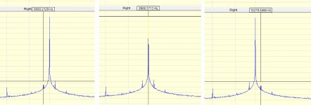
Can you measure accurately the frequency distance between side peaks and fundamental ?
Do you have the PCB mounted in a shielded box ?
Regards
Frex
Ok, fine.
Can you measure accurately the frequency distance between side peaks and fundamental ?
Do you have the PCB mounted in a shielded box ?
Regards
Frex
They are peaks from main supply.
Probably, your 1K have better shield from 10K unit.
Take the 10K unit away from this point of measuring and look the changes.
Probably, your 1K have better shield from 10K unit.
Take the 10K unit away from this point of measuring and look the changes.
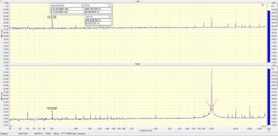
Yes, the oscillator is made clearly on your project.Do you have the PCB mounted in a shielded box ?
I will measure as soon as possibleCan you measure accurately the frequency distance between side peaks and fundamental ?
The modulation products seem to be about 300Hz from the peak, which suggests its not mains related, but an amplitude modulation effect perhaps? Or sidebands on the measuring system clock?
Here it isCan you measure accurately the frequency distance between side peaks and fundamental ?
Attachments
Hello,
OK. The IMD product is a 300Hz frequency. This could be the sixth harmonics of the main,
but it's a little bit curious. What others equipment are powered around it ?
Is there any transformers ?
May be you cant try to :
- Keep away any powered devices (if possible).
- Put the oscillator and it's battery in a metal enclosure (a metal cookies box is fine)
and show if this change the IMD product level.
Maybe you can post a picture of your full test setup also.
Regards
Frex
Hi Frex
I notice on your 1kHz Bom that LM317 U4 and LM337 U5 are at 0. Do we not need those on this project?
Regards
SImon
I notice on your 1kHz Bom that LM317 U4 and LM337 U5 are at 0. Do we not need those on this project?
Regards
SImon
Hello,
Please look at the document named "EOSC10KV3_History" at the root of design folder,
and page 2 of schematics.
The oscillator can be supplied using standard low cost regulator (LM317/LM337) OR
with low noise type regulators. Some others parts are different depending on regulators type is choose.
Note that both 1k/10kHz bom files are for low noise regulator version.
Regards.
Frex
Some time ago I put my hands on a board like this ... Thanks Frex!
I'm having trouble getting the results that others had better than <-120dBv.
I'm using my oscilloscope (FFT) and the best value I have is -65dBv and on my THD meter (MARCONI) (very old) the value is 0.05% THD.
Could someone help me to try to solve this?
Am I measuring wrong?


I'm having trouble getting the results that others had better than <-120dBv.
I'm using my oscilloscope (FFT) and the best value I have is -65dBv and on my THD meter (MARCONI) (very old) the value is 0.05% THD.
Could someone help me to try to solve this?
Am I measuring wrong?
Last edited:
Hello,
Start to check if nothing is wrong on time domain with the oscilloscope.
You must show a very clean sine-wave without spurious noise.
Check if there is no high frequency oscillation too.
What coaxial cable length do you use on output ? You have tried both outputs ?
What type of power supply is used ?
Do you have cleaned the PCB after soldering to remove all flux trace ?
I hope that help.
Regards.
Frex
Frex, Thanks for the reply.
The wave on the oscilloscope is clean and in high resolution. I did not find high frequencies in the signal.
My coaxial cable is 1m long.
The two exits have exactly the same signal.
I'm using a symmetrical bench source, but I've tested it with LiPo batteries and with the same results.
I have been trying to eliminate these Armonicas for some time and one of the things that is emphasized in the instructions is the cleaning of the PCI. It was very clean after assembly, but I have cleaned it twice more and the result remains the same.
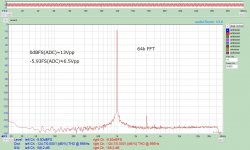
I would say you can't have more than 80dB THD with a scope because a scope usually employs a wide frequency range amplifier and high sampling rate ADC, where the best SFDR is probably 80dB. The best scenario to measure a low distortion oscillator is DSM ADC, like AD7768.
As long as I have tried, SAR ADC is superior to DSM one in SNR but inferior in THD. The pic is my measurement with AD7768. Mine can have better performance than this because I modified some filter values to stop high-frequency oscillation. I'm sure I still need some hacking.
As long as I have tried, SAR ADC is superior to DSM one in SNR but inferior in THD. The pic is my measurement with AD7768. Mine can have better performance than this because I modified some filter values to stop high-frequency oscillation. I'm sure I still need some hacking.
Attachments
You can't measure the limit of EOSC10Kv3 with that equipment that you have.
The Marconi the best THD is 0.01% with the right calibration, the Spectrum FFT of your oscilloscope probably is 8bit vertical resolution (!).
The Marconi the best THD is 0.01% with the right calibration, the Spectrum FFT of your oscilloscope probably is 8bit vertical resolution (!).
Thanks for the comments
xx3stksm...
I am clear that I will not get values lower than my noise floor. But the peaks of the harmonics that appear, are right above my noise floor.
Lemon ...
You're really right and i put it wrong ... My THD meter is Radford and its smallest measurement is 0.00001%. Sorry for the wrong information.
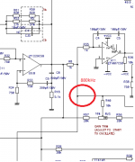
As both exits have the same signal, I believe that the problem with the harmonics must be something that is wrong for both exits.
In the image there is a point on the circuit where I found a frequency of approximately 880kHz and I don't know if this is correct.
Would anyone know how to say?
In the image there is a point on the circuit where I found a frequency of approximately 880kHz and I don't know if this is correct.
Would anyone know how to say?
Attachments
- Home
- Design & Build
- Equipment & Tools
- EOSC10Kv3 - LT AN67 10kHz oscillator : new updated version !