These diodes try to attenuate back emf across the output devices to supply rail + diode Vf.
They would conduct if the amp output were suddenly limited/cut off, or if the speaker and or speaker cables injected a current into the amplifier.
They are recommended for all ClassAB amps with I or IV limiting.
I also recommend two diodes from -ve supply to Zero Volts/Power ground to +ve supply. These only conduct if you apply PSU back to front or if one side of the amp gets shorted and the other half of the PSU tries to reverse charge the now discharge capacitors.
VI limiter
Greetings earthlings. I have been probing the universe for an eggs sample of the VI limiter, and bingo, I found one. One that I hope may solve the problem with the negative half of the wave in post #60.
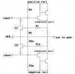
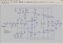
To explain what I mean I will refer to the circuit below.
I was using just R1 & R2 + R1a & R2a
Now I want to add another big resistor to reference either half of the circuit to it's appropriate rail, i.e. R3 to the Positive rail, and then, down below, R3a to the Negative rail. I reckon this will sort my problem out.
Any ideas?
Someone alluded to this resistor earlier I think but the idea went un-checked until I re-read this article today.
Now, the formula for a simple two resistor voltage divider is:
Vout = Vin * (R2/(R1+R2)) I think!
BUT is there a formula for the 3 resistor network shown below???? or should I just pop it onto the breadboard and do it by trial and error? 🙂
Greetings earthlings. I have been probing the universe for an eggs sample of the VI limiter, and bingo, I found one. One that I hope may solve the problem with the negative half of the wave in post #60.
To explain what I mean I will refer to the circuit below.
I was using just R1 & R2 + R1a & R2a
Now I want to add another big resistor to reference either half of the circuit to it's appropriate rail, i.e. R3 to the Positive rail, and then, down below, R3a to the Negative rail. I reckon this will sort my problem out.
Any ideas?
Someone alluded to this resistor earlier I think but the idea went un-checked until I re-read this article today.
Now, the formula for a simple two resistor voltage divider is:
Vout = Vin * (R2/(R1+R2)) I think!
BUT is there a formula for the 3 resistor network shown below???? or should I just pop it onto the breadboard and do it by trial and error? 🙂
Attachments
Last edited:
The Leach protection is a current limiter with an adjustable slope.
It needs one more resistor in the upper and lower halves to convert it to a VI limiter.
See Jens' Leach clone for where this extra resistor is located.
I'm sorry, it went over my head, until I saw an extra resistor in another circuit and now I think I may be on the verge of solving this little problem.
Yee Haargh
That third resistor makes it a dual-slope VI limiter. It lets you sail closer to wind as far as device limitations goes. Note that the circuit in post 82 lacks the emitter resistor needed for the doubled-up output transistors. You will the have two high-power resistors in your OPS to eat up those precious Watts.
To get around this, my last circuit uses the emitter resistor for current sensing instead of adding a collector resistor for the purpose. The approach of cutting off the pre-driver may be a better than the one I chose.
There might be another way and that is to use an optocoupler in the VI limiter, but I am still looking for a suitable optocoupler SPICE model to test it out. There was a thread on this topic very recently.
http://www.diyaudio.com/forums/solid-state/43331-power-amp-under-development-374.html
My last post explains the calculation of values for a VI limiter. For the circuit in post 82, the formula for a voltage divider only applies if the base current for Q1 is about a tenth or less of the current through R1.
Last edited:

Nope, according to LTspice, that one does not work. I'm still trying to figure it out. Here is my version of the circuit. I may have made a mistake, but I can't see one. It is quite late and cold here, I'll pursue it further tomorrow.
Attachments
Do yourself a favor and skip the vi limiter, all it does is making the amp sound bad just as Rod Elliott says on his web site.
I have never used a VI limiter in any of my circuits and never will.
A better option is sensing the current on the speaker output and use a led and ldr setup on the input to limit the input signal as the amp approaches the upper limit of the SOA.
This way distortion wont be affected as the limiting happens the same was as a volume control works.
Nope, according to LTspice, that one does not work. I'm still trying to figure it out. Here is my version of the circuit. I may have made a mistake, but I can't see one. It is quite late and cold here, I'll pursue it further tomorrow.
Voltage sources to the "other side" of R17/27(direct to OPS). OP stage is collapsing rails. 🙂 B-C 100pF cap across Q4 for CFP stability.
OS
Correction - that is not a dual-slope limiter. It is a bit more complicated than that.
This is:-
http://www.diyaudio.com/forums/solid-state/103632-cheap-100-150-watt-amp-15.html#post2475247
Brian.
Chute wont open
Do yourself a favor and skip the vi limiter, all it does is making the amp sound bad just as Rod Elliott says on his web site.
Ha ha ha. I reckon you're right about that one Tekko'. I am drawing up the boards now and guess what? No limiting except via volume knob! I didn't want to jump out of that plane - until it started burning.
I am going off air for a few days until I get this thing up and running.
Thanks for the tips.
Phil
Howdy Brian, nice to make your acquantance. I'll have a look at the spreadsheet, but the VIL has left a bitter taste! Will proceed without it.
Cheers, Phil
Salutations and Gratitude.
Nanu Nanu* Stripper. We have had some funny looking 'stars' in the sky down here, is this your Mother-Ship? If not, I'll have to make one of those foil hats to stop 'em from reading my circuits! God 'elp 'em if they do.
Do you mind if I copy your circuit, Substituting similar transistors? Just for my own use? This was one of the requests earlier in this rather unwhieldy thread. Yours will work nicely with my salvaged toroids. I have two of them, each is 200VA. They may be a bit on the smallish size, but they are in my junk bucket, so I dont want to buy more.
How many big caps should I use in my PS. I was thinking 10mF/rail/board, so that's a total of four of them, which equates to just one per secondary winding. I have another four if I need them.
Should I use your pcb drawing as well? !!!- while I'm on a roll.
Is there anything else you can do for me?
Cheers and thanks. Phil
*"Mork & Mindy"
I did not feel like fully simulating yours. But my "old amp" is just the reverse of yours (NPN input stage).
below , just copy the basic form (in reverse for yours - pnp input)
does nice .03% at 20k. 🙂
OS
Nanu Nanu* Stripper. We have had some funny looking 'stars' in the sky down here, is this your Mother-Ship? If not, I'll have to make one of those foil hats to stop 'em from reading my circuits! God 'elp 'em if they do.
Do you mind if I copy your circuit, Substituting similar transistors? Just for my own use? This was one of the requests earlier in this rather unwhieldy thread. Yours will work nicely with my salvaged toroids. I have two of them, each is 200VA. They may be a bit on the smallish size, but they are in my junk bucket, so I dont want to buy more.
How many big caps should I use in my PS. I was thinking 10mF/rail/board, so that's a total of four of them, which equates to just one per secondary winding. I have another four if I need them.
Should I use your pcb drawing as well? !!!- while I'm on a roll.
Is there anything else you can do for me?
Cheers and thanks. Phil
*"Mork & Mindy"
does nice .03% at 20k.
In the interest of truth in advertising, I should point out that your simulation was not at full rated power.
In the interest of truth in advertising, I should point out that your simulation was not at full rated power.
Right on. I just simulated it. I WOULD NOT build it. (again) 😀
(or advertise it.)
edit , to farmer .... add an extra transistor to the VAS (make a real blameless).
Reverse P for N in my example ( below). 68pF will be stable for the rest of the circuit .
PS- reconsider the CFP output for this amp. The EF2 is far more stable , easier to thermally stabilize , as well. Layout and decoupling of a CFP is also "picky" like a triple EF.
OS
Attachments
Last edited:
Hi,
Agreed.PS- reconsider the CFP output for this amp.
Pickier. It`s pretty meaningless to simulate this topology, build and see if you can get it stable, you probably can`t. Anyway, you`ll most likely dislike the sound.a CFP is also "picky" like a triple EF.
Farmer Jack's original design had a CFP and we stuck to that. Along the way it did show its weaknesses. Might be worthwhile to do a sim to compare the distortion produced by CFP and EF.
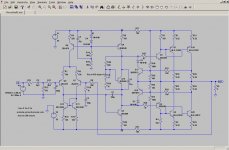
And here is a version with an emitter follower output stage. THD at 160W into 8ohm at 1kHz is 0.0026%. At 20kHz it is 0.029%.
Any resemblance to Douglas Self's Blameless amp is by design.
Any resemblance to Douglas Self's Blameless amp is by design.
Attachments
Last edited:
And here is a version with an emitter follower output stage. THD at 160W into 8ohm at 1kHz is 0.0026%. At 20kHz it is 0.029%.
Purfect ! Just 1 - 470r resistor to the collector of Q13 to keep it from burning up at clip , 33-47R at collector of Q5 for stability(degeneration) , adjust R6 for 8-10ma CCS ,base of Q1-2 /14-15 2.2R-4.7R "basestopper" to also increase stability. Good to go.
Now that you have a amp with >100db open loop gain , careful w/compensation.
Even w/ 100pF Cdom, 15R at input pair Re is a bit low. 2240/970 is real close to my 1845/992 devices. I had outright oscillation with 10-20R here.
100pF/ 47R or 68p/100R (R7-8) would bring you in the "ballpark" of 500k unity gain point - acceptable margin.
OS
Last edited:
- Status
- Not open for further replies.
- Home
- Amplifiers
- Solid State
- Engineer, help please - Neg. feedback/infilters