A fuse does the same thing only its 100 to 1000 times slower, the circuit i mentioned uses a relay and a few transistors and disconnects in a matter of milliseconds while a fuse can take up to several minutes or even hours to blow.
Keep in mind that a fuses rating is a current it can withstand for atleast a hour, few Amps above its rating its 20-30 minutes and only above that it starts getting down to seconds.
Even with a 300+ watt amp, the fuse would have to be only 1-3A in order to provide any protection what so ever against amp failure DC output to the speaker, often the speaker cooks long before the fuse blows, usually it happens once the speaker gets so hot that the coil shorts out.
I've built this circuit and it works just as intended:
Last edited:
Is this one ready to go?
You don't need resistors on the collectors and emitters of the output transistors. Only the latter is needed.
What is Output DC Protection? I have a fuse going to the speaker, do I need something else before I lay the board out?
A fuse will not do much good. To be effective, you will need to think long and hard about the rating. Too little and it will just blow unnecessarily. Too much and it will be protected by the output transistors, i.e. it will not blow. Even just right does not help, since then the thing will heat up and change its resistance, i.e. you now have a non-linear element sitting in your signal path.
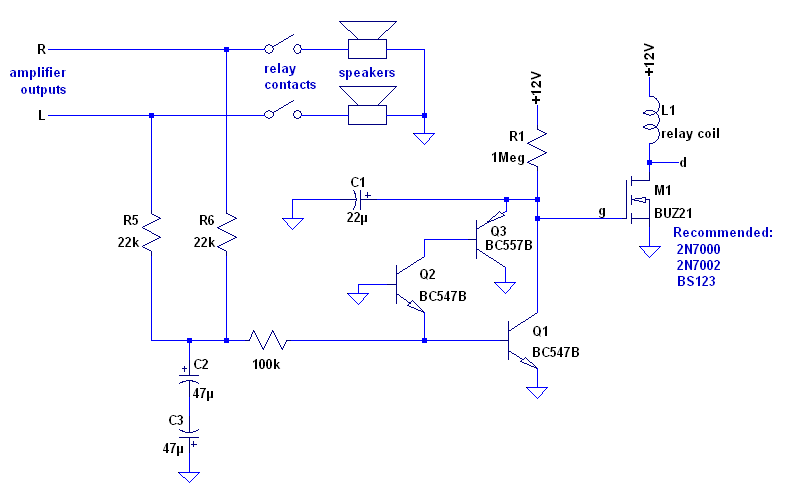
The way around this is to put a relay in there. You then have a few diodes and caps to detect DC and drop the relay when needed. Here is an example, but there are many variations on this. The output labelled "Off" goes to the relay coil.
An externally hosted image should be here but it was not working when we last tested it.
You can also add overload protection to this relay circuit, as well as soft start and stop (to mute the thump when you turn the amp on and off). You have to be careful and not use a relay that is too small, otherwise the contacts will eventually weld themselves together and nothing will be protected. Such relays are not cheap, unfortunately. You could use a couple of great big MOSFETs in place of the relay, but the jury is still out on that one.
Last edited:
I disagree.Here is the latest version. I'm sorry but that 220pF cap in the input stage had to go. It's not really needed anyway as the frequency response is controlled elsewhere and it just interferes with that.
That input filter of 220r + 220pF is the main RF filter and limits the "speed" of the input signal. It also loads the input stage with a HF low impedance.(i.e. the input base pin sees the 220pF to ground as a low impedance load).
In my view it is mandatory.
All that one should do is experiment with component values for R & C.
I've built this circuit and it works just as intended:
[/QUOTE]
- Do I use the 'normally-open' switch on the relay?
- Is that coil energised during normal amplifier operations?
A fuse will not do much good. To be effective, you will need to think long and hard about the rating. .....................................................You could use a couple of great big MOSFETs in place of the relay, but the jury is still out on that one.
The relay is good insurance but it must be augmented with low value fast fuses in both supply rails. The relay can break low current to the load, big currents are broken by the fuses. Fit a pair of F2A fuses in the supply rails for an effective maximum audio signal to the load of ~4Aac, i.e. <=128W into 8ohms, or F3A for <=288W into 8ohms.
There is a thread running now that discusses in detail how to overcome the main limitation of output relay protection. The relay cannot break big DC currents !!!
yes the NO contact is used to connect output to speaker terminal. Don't use a standard diode across the relay coil to suppress back emf. It slows down the relay release too much. Add a Zener in series with the diode. The Zener value is ~ = relay coil voltage rating.I've built this circuit and it works just as intended:
- Do I use the 'normally-open' switch on the relay?
- Is that coil energised during normal amplifier operations?
The relay coil will run cooler if you arrange for a lower running current through the transistor switch and the relay coil. Aim for about half the nominal coil current (requiring half the nominal voltage) for long term active operation. The relay cannot trigger reliably at this lower power, so the trigger voltage needs to be "boosted" to guarantee triggering. This "boost" and Low current requires just two extra components R+C costing pennies.
The lower running current also helps the relay open more quickly in event of fault.
Last edited:
Add a Zener in series with the diode. The Zener value is ~ = relay coil voltage rating.
The relay cannot trigger reliably at this lower power, so the trigger voltage needs to be "boosted" to guarantee triggering. This "boost" and Low current requires just two extra components R+C costing pennies.
The lower running current also helps the relay open more quickly in event of fault.
Hello again Andy. When you get a chance could you please take a look at the circuit below, I'm a little bit unsure about the orientation of the Zener.
I have adapted your circuit for my relays they have 5V & 28 ohm coils with a spst 30A N.O. switch. I have to use two devices for the job so I connected both coils in series. 2N7000's didn't quite squeeze in to the power margin. Ill try an IRF630 Mosfet.
Coil Power, How low can I go? Ok the two series coils are now passing around 100mA at a voltage of close to six. The contacts in the switches clack in and out ok as expected - no load on the switches. The relay datasheet states that the nominal current is 185mA & 5v for one coil. I will have to test the circuit under load to see if she does the old click-clack.
Cheers and bye for now, Phil Elliott
Attachments
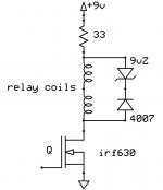
9Vdc for a pair of 5V relays in series is too low. Adding a 33r resistor makes that problem worse. If the 9V drops for any reason or is slow to reach full voltage at start up then the relays may not trigger.
Add an electrolytic to your schematic. The +ve lead goes to the top of the relay coil.
The -ve lead goes to the Source of the mosFET. A 200V device here is a waste, any 200mA, 30V or more BJT or FET will do as a switching device.
While the FET is open, the cap charges to the supply voltage, whether it's 8Vdc or 9Vdc and holds that charge until the FET conducts.
The cap sends a short current pulse into the relay coils that triggers them. This pulse only needs to last as long as the datasheet time for "ON", usually of the order of 3ms to 15ms. Try a 33uF 25Vdc cap.
If you can, increase the supply voltage to >=10Vdc. I tend to use 1.5Times to 2Times the rated coil voltage. Then adjust the resistor to bring the "ON" voltage down to about 50% of rated coil voltage. This ensures a fast and positive "ON" that never fails if the supply is slightly low or slightly slow to reach operating voltage.
The resistor can run pretty hot. Use enough dissipation capability.
Last edited:
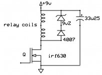
Does this one look a bit better?
I didn't anticipate the required voltage-margin-overhead. A safe buffer.
That 9V in the schematic is 1/2 of my dual rail 'preamp power supply', I can invoke the negative half, if required to give me 18VDC - then use a resistor. Or I can use a different transformer, - I have quite a selection of the small pcb mount devices - all recovered from the tip! Not that I'm tight or anything.
Thanks and Bye for now. Phil
Attachments
Finished Spkr Protect
Here is the circuit given to me. Don't know what the zener does but I guess it just takes the tops out of the BEMF spikes, thus limiting the pulse that goes back into the positive rail?
Recommended nominal current for each relay is 185mA but according to instructions I have cut it back to about 110mA. Any less and I can tell that the contacts are not switching solidly.
Can someone give it a quick once over.
Cheers. Phil
Attachments
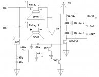
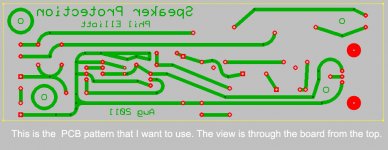
You may wanna thicken the traces for the audio signals since these can carry quite a bit of current.
Heres a pic of my dc protect board, with a thermal shutoff included(the second relay): http://i.imgur.com/TLeHK.jpg
Heres a pic of my dc protect board, with a thermal shutoff included(the second relay): http://i.imgur.com/TLeHK.jpg
Last edited:
It doesn't look to me like those zeners will ever zener unless the rectifier shorts. Superfluous part?
Tricky thing about relays, the hold current can be much lower than the actuation current. Its not totally necessary that you get a big Thwack out of it, if the magnetic gap manages to close reliably and stay there, the spring pressure on the contacts will be the same no matter how much coil current.
Tricky thing about relays, the hold current can be much lower than the actuation current. Its not totally necessary that you get a big Thwack out of it, if the magnetic gap manages to close reliably and stay there, the spring pressure on the contacts will be the same no matter how much coil current.
Last edited:
Heres a pic of my dc protect board, with a thermal shutoff included(the second relay)
I assume the circuit is as in post 122. And while I am imposing on you, a picture of the bottom of that stripboard would be swell.

Thanks. I've been wondering about stripboard myself. Working out what goes where and constructing it is sometimes such an effort that one might as well lay out a PCB.
PCB
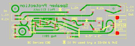
Hi there J: I have checked the pcb several times and it reckon it matches the circuit drawing, I just wanted to show off my new CAD drawing skills! Here is the pcb pattern looking from the top, without the components. Have a good weekend.
Phil
Hi there J: I have checked the pcb several times and it reckon it matches the circuit drawing, I just wanted to show off my new CAD drawing skills! Here is the pcb pattern looking from the top, without the components. Have a good weekend.
Phil
Attachments
circuit
It is a work of art and it artfully works! See how much faith I have in you fellows!
Thanks again. Phil
It's a bit of a mess, but it works well: http://i.imgur.com/675lM.jpg
It is a work of art and it artfully works! See how much faith I have in you fellows!
Thanks again. Phil
Hi,Here is the circuit given to me. Don't know what the zener does but I guess it just takes the tops out of the BEMF spikes, thus limiting the pulse that goes back into the positive rail?
Recommended nominal current for each relay is 185mA but according to instructions I have cut it back to about 110mA. Any less and I can tell that the contacts are not switching solidly.
Can someone give it a quick once over.
Cheers. Phil
in the previous post you reduced the 33r resistor to 0r0 to account for the 9V supply.
This diagram shows a 12V supply so the resistor value can be increased above 0r0. But you have the 33uF cap tapped in above the resistor. It should be tapped in to the top of the relays.
- Status
- Not open for further replies.
- Home
- Amplifiers
- Solid State
- Engineer, help please - Neg. feedback/infilters