how to?
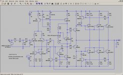
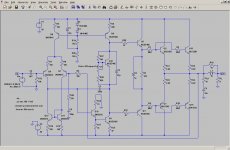
1. add command - .ac dec 100 1 10e6
...this will sweep from 1hz to 10Mhz at 1v
2. add voltage source between output and feedback resistor , add "1" in "small signal ac analysis" box.
3. add 1 "label net" (next to ground at top) of "Vout" at output and another labled "A" before voltage source next to feedback R.
4.simulate , in plot box .. right click> "add trace" ... then paste " -V(vout)/ V(a) " below you see output.
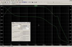
To interpret readout - click on expression , move axis to 0db. Phase should be (-)90-105 , leaving 90 -75 "margin". The "edge of the cliff" in phase plot should not fall off for >200 khz after the 0db point. example below shows a typical response.
EDIT - amp is over -10db negative gain , where the phase "falls off the cliff" - stable as rock.
OS
1. add command - .ac dec 100 1 10e6
...this will sweep from 1hz to 10Mhz at 1v
2. add voltage source between output and feedback resistor , add "1" in "small signal ac analysis" box.
3. add 1 "label net" (next to ground at top) of "Vout" at output and another labled "A" before voltage source next to feedback R.
4.simulate , in plot box .. right click> "add trace" ... then paste " -V(vout)/ V(a) " below you see output.
To interpret readout - click on expression , move axis to 0db. Phase should be (-)90-105 , leaving 90 -75 "margin". The "edge of the cliff" in phase plot should not fall off for >200 khz after the 0db point. example below shows a typical response.
EDIT - amp is over -10db negative gain , where the phase "falls off the cliff" - stable as rock.
OS
Attachments
Last edited:
Thanks for the input, ostripper. I will have another go at it.
I have also figured out how to get the VI limiter right for the topology discussed earlier. It's just a matter of tweaking the current limiter in the voltage amplifier stage. That will bring better results than trying to fiddle with the one in the output stage. These two actually work together.
I will report back later. Right now I have to go the shops to pick up a few things for a loudspeaker project. 😉
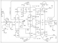
Here is the revised version of the circuit in post 59. I erroneously called Q18 an active load for Q5. It is in fact another VI limiter.
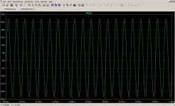
The current limits of the posive and negative half cycles are now nicely in balance. Unfortunately performance is curtailed by all of this. Even into an 8 ohm load the waveform is not symmetrical.
It seems that we either accept the asymmetry in current limiting, or we ditch the VI limiter and look at other forms of amplifier and speaker protection.
Attachments

Last edited:
As for the circuit in post 99, I'm still scratching my head. Phase margins e.a. is the hard part...
A protection system must allow all valid signals to pass to all valid loads
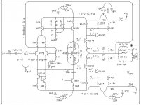
What is the quiescent (bias) current through Q5? It is set by R6.
What is the range of operating current of Q5 when passing audio signal?
What is Q18 doing while the current through R26 tracks the current flowing through Q5.
This VAS protection cannot do it's job properly with the component values shown.
The post above goes to show that symmetric current limitation only brings about other problems. It was something touched upon earlier in this thread. Without the VI limiter the circuit is fine. It will probably work better if the current limit is set at a higher value. Life is full of compromises.
Building an amp with a 110V supply is not trivial. The limit of 6A into a short circuit is not quite enough to ensure that the output transistors will survive, as can be seen in the SOA curve from the datasheet. The only way around this is to add more devices in parallel. Do we do that or look at other mechanisms such a relay?
Attachments

Last edited:
I've been putting the EF circuit through the mill. Just to be sure that the simulation is as accurate as can be, only models from Bob Cordell's website were used (as indicated by the C suffixes). At this stage I've ditched the original signal conditioning input stage and made changes to the feedback network resistances. With a small modification we can probably be get back to the original values. Whee, this is fun! 😀
Attachments
Last edited:
With a +-55Vdc supply the likely maximum voltage at the output before the rails sag is ~48Vpk.
8r0 will draw ~6Apk, 4r0 will draw ~12Apk.
While the output is momentarily @ 48Vk there is approximately 7V across the output device less other voltages losses through the other components. Lets assume a 5Vce value and 6Apk current for 100ms until the fuse blows or the Rails sag or the capacitors discharge or whatever.
Now compare 5Vce & 6Apk to the 25degC SOA.
Hold on, what is the temperature of the amplifier when that peak voltage and peak current hit those values? De-rate the SOA to operational temperature of the device cases (Tc).
Now repeat for a 4r0 load.
Now look up how complicated it becomes when the load is reactive.
Read David Eather.
A 8 ohm speaker will typically dip down to 6-7 ohms at some frequencies and sometimes as low as 4 ohms.
Same for a 4 ohm load, but the dips can reach as far down as 1-2 ohms with some speaker models. Now these dips doesent really pose any threat with fullrange speakers as we never go much above 5-10 watts anyways.
But on subwoofers on the other hand, they often use most of the amplifiers output capability, much why properly built subamps have up to 10x the quantity of output transistors for the same output power as a fullrage amp having only a single or dual pair output.
I'd skip all protection circuits except for the dc protect on the output.
These limiting protect circuits are not needed in a hifi amp since its not gonna get pushed in any way.
Limiting circuits are only necessary in amplifiers that are likely to ba daily working near their limits such as PA gear and subwoofers used by teenagers that like to do SPL contests.
For a hifi amp in a normal size home, a limiting protect circuit just doesent justify the cost of the extra parts. Not even my 300W subwoofer amp im building is gonna have a limiting protection circuit, just the output dc protect.
Only protection i use is the output DC protect circuit.
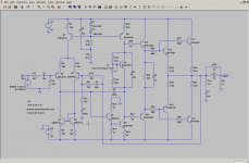
Here is the latest version. I'm sorry but that 220pF cap in the input stage had to go. It's not really needed anyway as the frequency response is controlled elsewhere and it just interferes with that.
The 220pf suppresses radio frequencies.
You dont want an amp that receives radio broadcasts !
I use a 82pF cap there, works well, doesent interfere with audio freq, yet supresses radio frequencies.
Output DC protection
Is this one ready to go?
Will ceramic caps do ok for the input filter and VAS filter?
Are the voltages for the electrolytics ok? Do any need to be NP?
What is Output DC Protection? I have a fuse going to the speaker, do I need something else before I lay the board out?
I use a 82pF cap there, works well, doesent interfere with audio freq, yet supresses radio frequencies.
Is this one ready to go?
Will ceramic caps do ok for the input filter and VAS filter?
Are the voltages for the electrolytics ok? Do any need to be NP?
What is Output DC Protection? I have a fuse going to the speaker, do I need something else before I lay the board out?
Attachments
- Status
- Not open for further replies.
- Home
- Amplifiers
- Solid State
- Engineer, help please - Neg. feedback/infilters